EasyManuals Logo

Planmeca ProX Technical Manual

Planmeca ProX
74 pages
To Next Page IconTo Next Page
To Previous Page IconTo Previous Page
Page #66 background imageLoading...
Page #66 background image
10 PARTS REPLACEMENT & REPAIR
64 Planmeca ProX Technical manual
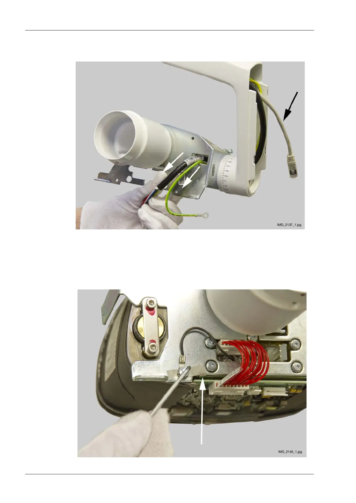
15.Route the arm cable through the tube head joint (white arrows). Leave the Ethernet cable
to the tube head support (black arrow).
16.Place the tube head to its position. Attach the upper tube head attachment screws using a
2.5 mm Allen key. Place the tube head PCB to its position and connect the cables. Attach
the protective lead to the tube head using a 2.5 mm Allen key.
17.Attach the potential equalizer lead and PCB grounding plate to support frame with an
attachment screw using a 2.5 mm Allen key. Note the position of the PCB grounding plate
(white arrow).

Table of Contents

Other manuals for Planmeca ProX

Questions and Answers:

Question and Answer IconNeed help?

Do you have a question about the Planmeca ProX and is the answer not in the manual?

Planmeca ProX Specifications

General IconGeneral
TypeIntraoral X-ray
Tube current7 mA
Imaging TechnologyDigital
Focal spot0.4 mm
X-ray generatorHigh-frequency
Power Requirements100–240 V AC, 50/60 Hz
Tube voltage60-70 kV

Related product manuals