7.33
FINAL DRIVE
7
9923412 - 2012 Sportsman 400/500 and EFI Tractor Service Manual
© Copyright 2011 Polaris Sales Inc.
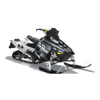
12. Pull outward sharply on CV shaft assembly to remove
it from the gearcase. In some instances, the splines
may be corroded, making removal difficult. A slide
hammer or other suitable device may be required for
removal.
Installation
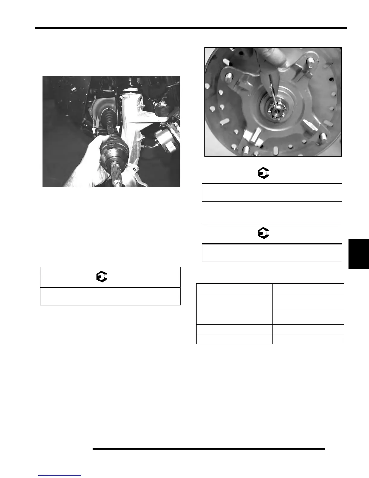
1. Install new compression ring on drive shaft. Apply an
anti-seize compound to splines. Align splines of drive
shaft with front gearcase and install by lightly tapping
on drive shaft with soft-faced hammer.
2. Install drive shaft in strut.
3. Install lower ball joint, torque
nut to specification and
install new cotter pin.
4. Install hub and tighten hub nut to specification.
5. Install brake caliper and tighten bolts to specification.
Re
fer to Chapter 9.
6. Install wheel and tight wheel nuts
to specification.
Refer to the beginning of this chapter.
Ball Joint Retaining Nut Torque:
30 ft. lbs. (41 Nm)
Front Hub Retaining Nut Torque:
60 ft. lbs. (91 Nm)
Brake Caliper Fastener Torque:
18 ft. lbs. (24 Nm)
Item Specification
Steel -
Front and Rear
Wheel Nuts
27 ft.lbs. (37 Nm)
Aluminum -
Front and Rear
Wheel Nuts
30 ft. lbs. + 1/4 Turn
(41 Nm + 1/4 Turn)
Front Hub Retaining Nut 60 ft.lbs. (81 Nm)
Rear Hub Retaining Nut 80 ft.lbs. (108 Nm)
 Loading...