THE ART OF WELDING
P6 HW
PN-0110008 Rev. 12 37-100
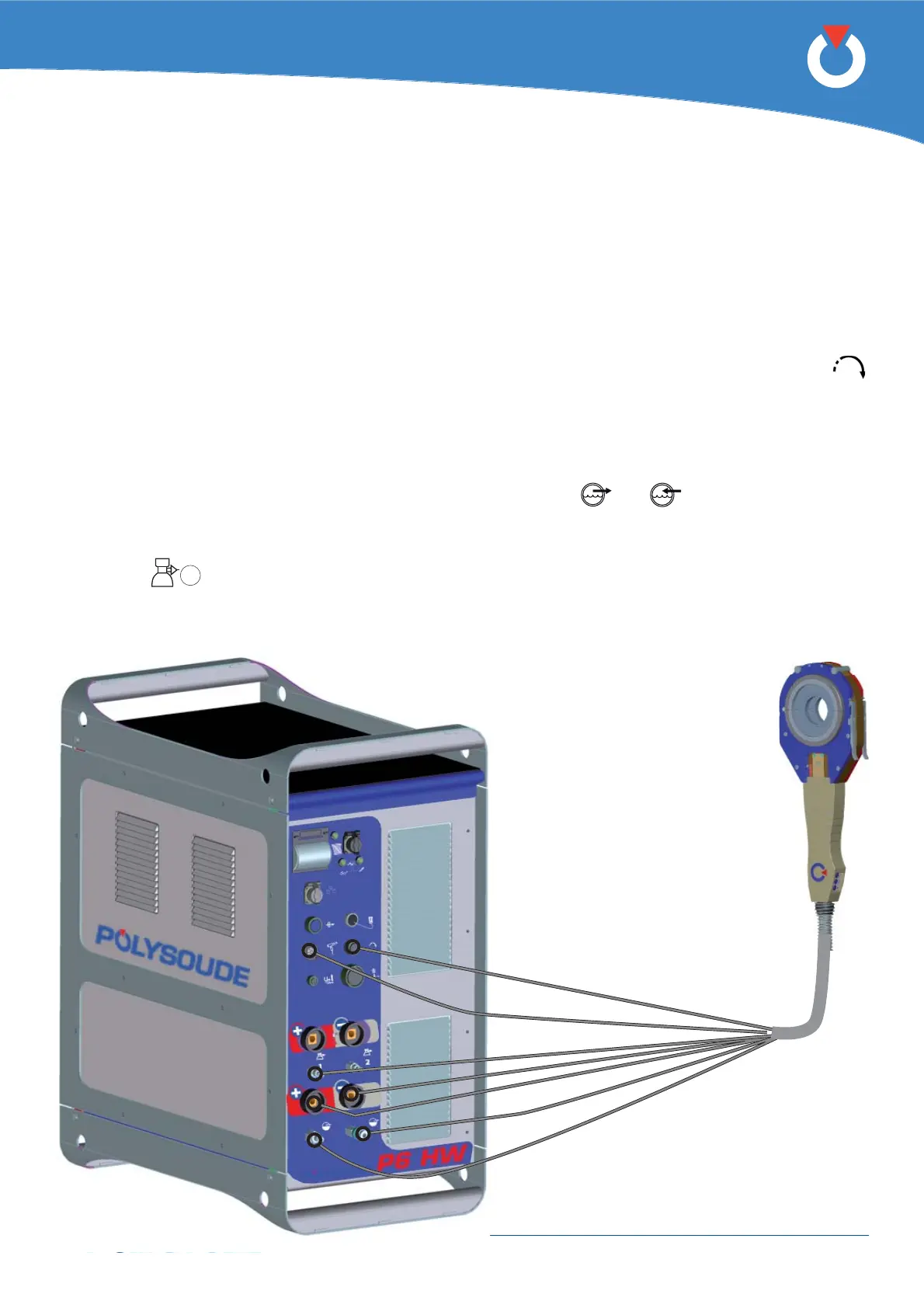
Fig. 4.12 - Connection of a liquid cooled closed
chamber welding head with integrated
command buttons
Connection of a liquid cooled closed chamber welding head with integrated command buttons (MW 4. 3. 6.
40-3, 65-3, 115-3, 170)
Connection of the electrode current cable
Connect the current cable on the “-” terminal with the quick connector, locking it by rotation to the right.
Earth cable connection
Connect the earth cable to the “+” terminal on the connector panel. The terminal is surrounded by a red ring.
Connection is made with a quick-fi t connector, locked by turning clockwise. The cable end is marked red.
Connection of the rotation motor cable
The wire feed unit is connected at the front connection panel of the P6 HW by a screw connector (symbol
). Make sure that the securing ring is properly tightened, otherwise the system may not function correctly.
Connection of the integrated control cable for new version type MW heads
Connect the integrated control cable to the “manual torch” terminal (connecter FA 5) of the connection panel with
connection ref 0023000901.
Connection of the cooling circuit
Connection is made by 2 quick couplings on the front panel (symbols
and ).
Connection of the torch shielding gas
Connection is made with a quick push-pull coupling on the connector panel.
(Symbol
1
).