THE ART OF WELDING
P6 HW
4
2
3
1
3
1
2
70-100 PN-0110008 Rev. 12
Maintenance and troubleshooting6. 2.
Replacement of fuses6. 2. 1.
A blown fuse often indicates that
there is a fault. Take great care
when switching on the machine
after a fuse has been replaced.
Fuse FU1 with a time delay of 4AT (Fig 6.2 - 1) for all
auxiliary power supplies is located on the upper right
side of the power source.
Fuses FU2 (Fig. 6.2 - 2) and FU3 (Fig. 6.2 - 3) with
time delay 16AT for the power supply to the prima-
ry of the transformer for the auxiliaries and the “hot
wire” current source area located on the right of the
rear panel of the power source.
Fuse FU4 (Fig. 6.3 - 4) with time delay 1.6 AT for
transformers T2 and T3 is located on the lower left-
hand side of the power source.
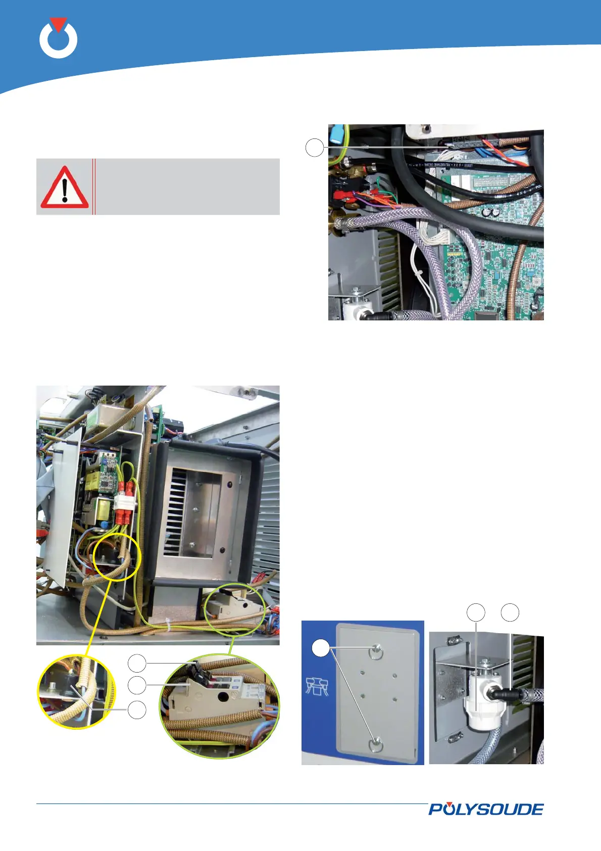
Fig. 6.4 - Coolant fi lter
Cooling circuit fi lter6. 2. 2.
The P6 HW generator is fi tted with a fi lter in the
cooling circuit. We recommend checking the cleanli-
ness of the fi lter element every 6 months.
The fi lter element is accessible after undoing by a
1/4 turn the two fasteners (Fig. 6.4 - 1) securing the
inspection hatch in the rear panel.
Place a container below the fi lter beforehand. Unscrew
the transparent or white housing (Fig. 6.4 – 2) and
take the fi lter element out for cleaning or replace-
ment.
For better accessibility, disconnect the two unions by
pulling the pressed fl ange (Fig. 6.4 – 3) upwards and
lowering the two hose end fi ttings.
Fig. 6.3 - Location of fuse FU4
Fig. 6.2 - Location of fuses FU1, FU2 and FU3