THE ART OF WELDING
P6 HW
BT 8
BT 9
BT 11
BT 10
56-100 PN-0110008 Rev. 12
Fundamental procedures5. 1.
Switching on5. 1. 1.
With the installation connected (see chapter 4), set
the switch FA 1 (Fig. 4.18) to position 1. After a
short moment, the power source is powered up and
ready for operation. The remote control unit display
must show information on the WPs and programs.
Comment: if the power source is equipped
with the emergency stop function, the opera-
tor control unit must be connected to the P6
HW, otherwise the latter will not power up.
In case of problems, see chapter 6.2 Maintenance.
After the power source has
been turned off by the switch
FA 1, wait for a time period of
at least 15 seconds before turn-
ing it on again.
Equipment recognition5. 1. 2.
Depending on the date of manufacture, the P6 HW
power source can detect the types welding heads or
wire feeding units connected automatically.
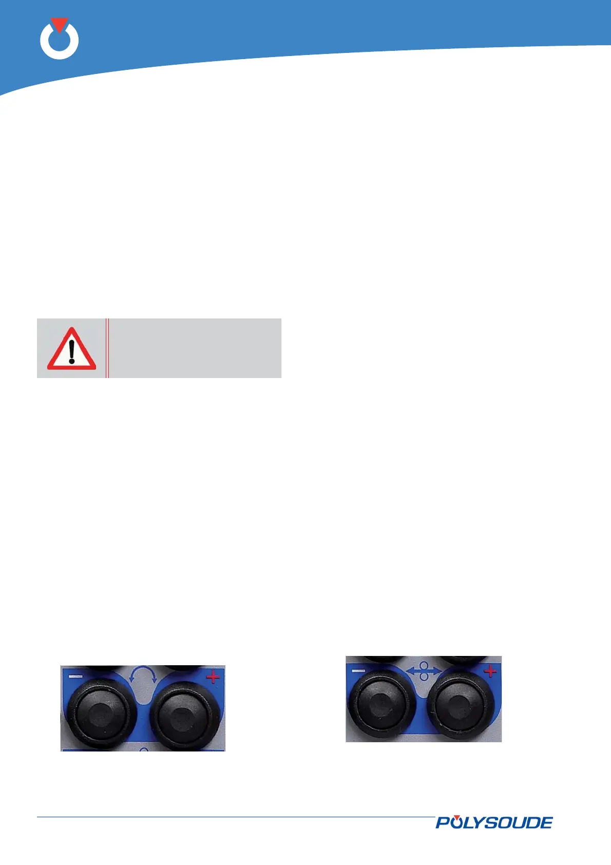
Fig. 5.1 - Controls used for positioning the electrode
Positioning a welding head on the workpiece5. 1. 3.
In order to position the POLYSOUDE welding heads
on the part to be welded, refer to the instructions
supplied with each head. With the welding head
in place, and before beginning the weld cycle, you
may move the electrode manually to wherever you
wish using the buttons BT 8 and BT 9 of the remote
control unit. Attention: with some closed chamber
welding heads the cycle cannot be started unless the
electrode is in the “open head” position.
The command is carried out in 3 stages: for 1 second
the rotation is made at low speed, then for 2 seconds
the rotation changes to medium speed, afterwards it
continues at high speed. This permits accurate and
rapid positioning.
If the welding head is equipped with a contact to
detect its “open” position, manual rotation stops
when the “open” position is reached. Release the
button then press it again to continue rotation.
Wire setting5. 1. 4.
To adjust the wire, two pushbuttons are provided on
the remote control: BT 10 and BT 11. Both of these
buttons, used with the “Auto/Manual Wire” switch
BT 12 (V 5 & V 6) allow the user to position the
wire accurately.
If the switch is in the “Auto” position, press-
ing one of the buttons causes the wire to advance
(BT 10) or retract (BT 11 ). The command is carried
out in 3 stages: for 1 second the wire advances at
low speed, then for 2 seconds wire feeding chang-
es to medium speed, afterwards it continues at high
speed. This permits accurate and rapid positioning.
To stop the wire, release the button.
If the switch is in “Manual” position, the wire
retract button BT 11 works in the same way, but the
advance button works in toggle mode: The fi rst press
starts the wire feed in high speed, the second press
stops it. This feature is particularly useful for insert-
ing fi ller wire into the wire-guide sheath.
Fig. 5.2 - Controls used for positioning the fi ller wire
Using the P6 HW power source5.