THE ART OF WELDING
P6 HW
BT 1
BT 2 BT 3
BT 4
BT 15
BT 5
V 4
V 3
58-100 PN-0110008 Rev. 12
Use5. 2.
Safety instructions5. 2. 1.
Before starting any manipulation
on the equipment please refer to
chapter 1 “Safety precautions”.
Program selection5. 2. 2.
The WP and the program to be executed are selected
with BT 1, BT 2 and BT 3 on the remote control unit.
The names of the WPs and the program selected are
shown on the remote control unit display and on
the home page of the touchscreen. After 2 seconds
without operator action the WP or program is loaded
and can be used.
A long press (> 2 s) on button FA 16 will print out
the selected program.
Fig. 5.6 - “Simulation / With Arc” indicator lights
Simulation5. 2. 3.
In order to check the programming without any
risk to the parts to be welded, you can fi rst run a
simulation cycle. In this case, all the functions of the
program are carried out except those concerning the
arc.
The gas commands that you have programmed are
executed but no account is taken of any fl ow rate
errors. In this way, you can, if you wish, check the
fl ow rate settings or save gas during the simulation
phases. Selection of a simulation is made with BT 4
which illuminates V 1.
Fig. 5.5 - Controls used for selecting the WP/pro-
gram
Weld cycle5. 2. 4.
Running a welding cycle
A weld cycle is started by pressing • BT 15 on the
remote control unit.
Fig. 5.7 - Pushbutton to control cycle
start
Making adjustments during a weld cycle.
During a welding cycle you can make adjustments
to the parameters very easily. This is done using the
remote control.
Parameter values which can be modifi ed within each
sector:
The current (• I22) and/or the back ground cur-
rent (I23) in the case of pulsed current.
The rotation speed • (V32) and/or the low rota-
tion speed (V33) in the case of pulsed rotation.
The wire speed • (V42) and/or the low wire speed
(V43) in the case of pulsed wire.
The AVC (• H50) the height.
The oscillation • (T63) left edge delaying (T62)
right edge delaying (V60) the gap (A62) the
amplitude.
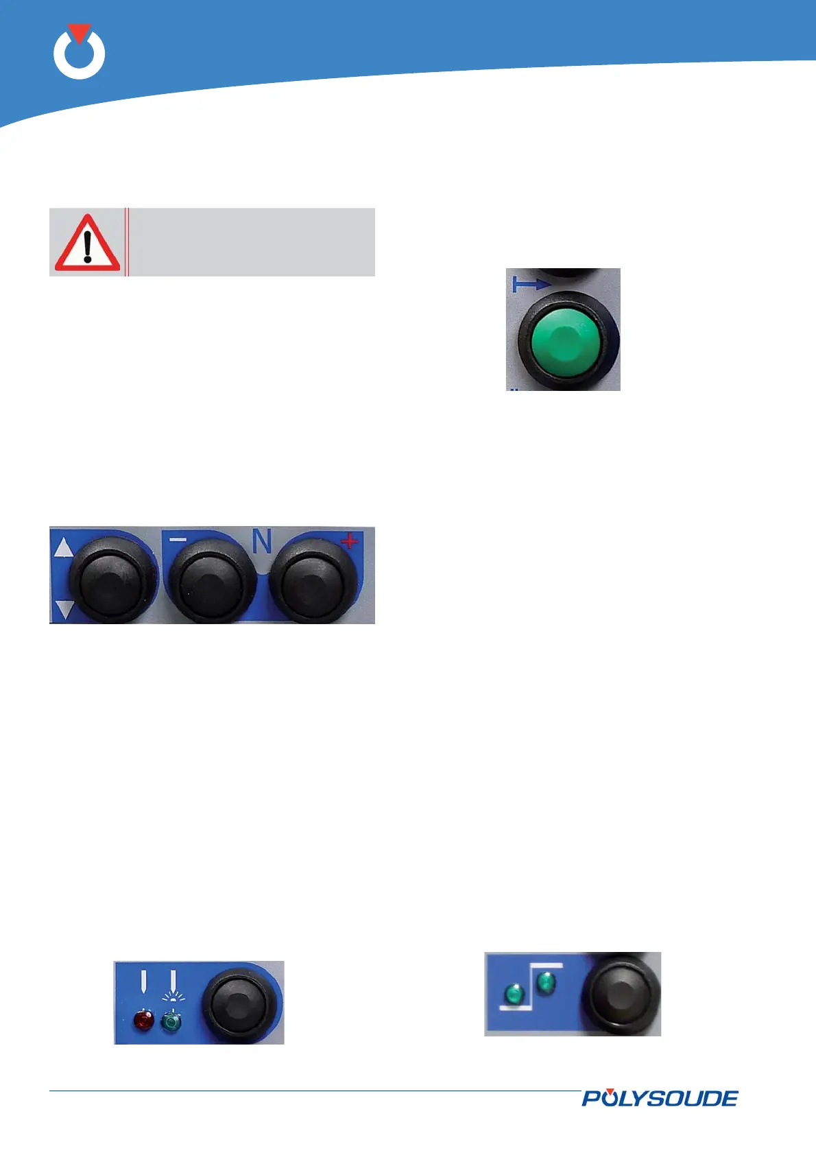
The modifi ed parameter values can be confi rmed
with BT 5 in conjunction with the 2 indicator lights
V 3 and V 4:
V 3• illuminated: Modifi cations of the low levels.
V 4• illuminated: Modifi cations of the high levels.
V 3• & V 4 illuminated: Modifi cations of the low
and of the high levels.
Fig. 5.8 - Pushbutton for tuning during
the cycle