EasyManua.ls Logo

Potter PFC-6800 - Isolator Device Load Calculation; Scenario 1: Class a Loop - Isolated Devices Configuration

Potter PFC-6800
133 pages
Print Icon
To Next Page IconTo Next Page
To Previous Page IconTo Previous Page
Loading...
2-14

Isolator Device Load Calculation



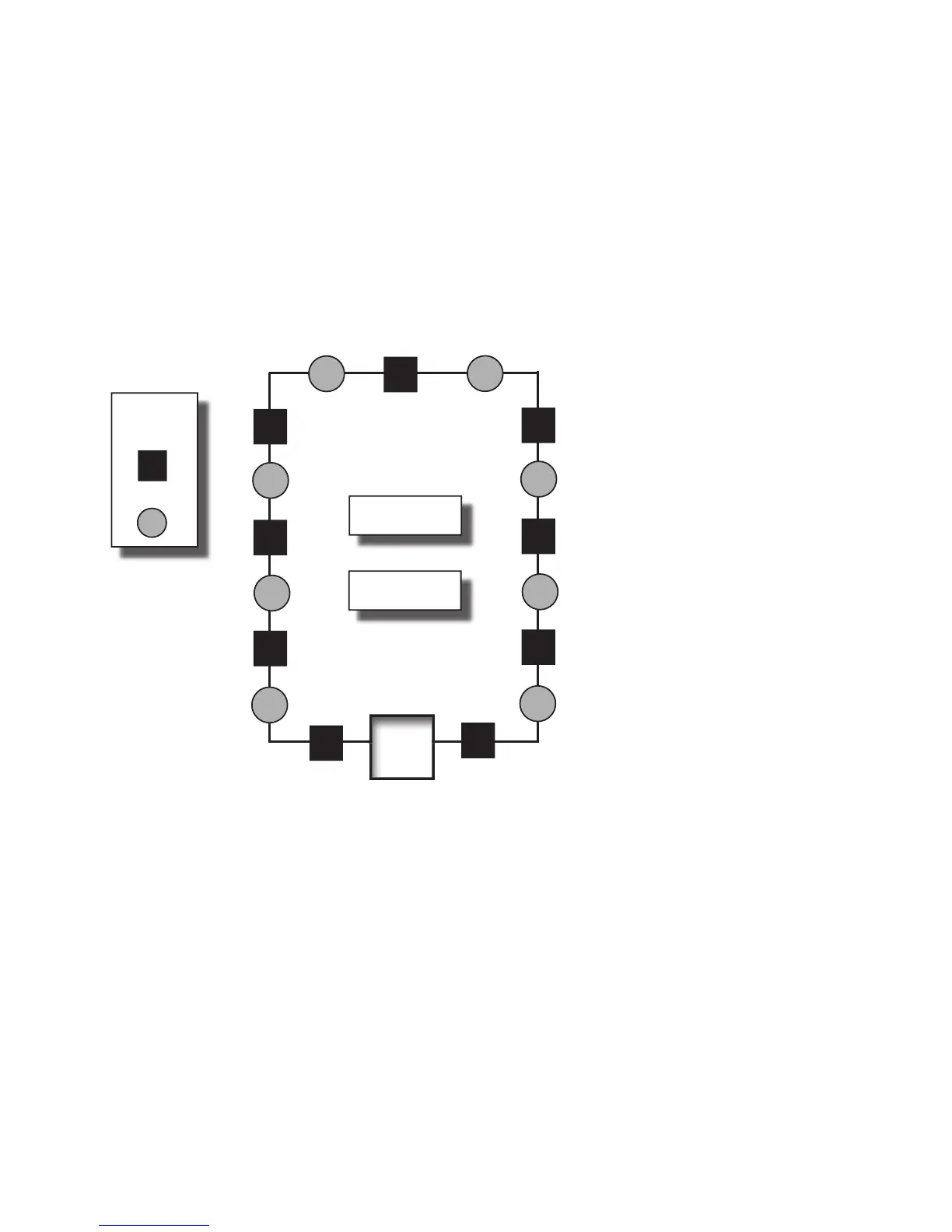
Scenario 1: Class A Loop – Isolated Devices Conguration

Formula: Total # addressable devices + Total # isolators = Total power unit allocations (or device load)
Example of a Class A Loop – Isolated BranchesFigure 3.
Conguration Summary:
Total addressable devices = 8 (sensors only) out of 127 possible addressable points.
Total device load = 17 (calculated as follows: 8 sensors + 9 isolators) out of 127 power unit allocations.
Example: If a conguration uses 75 sensors, up to 52 isolators may be supported.
Solution: 127 - 75 = 52
LEGEND:
ISO Module/
Device
Sensor
PANEL
To tal addressable
devices = 8
To tal isolators = 9
DWG # 593-4

Table of Contents

Related product manuals