EasyManua.ls Logo

Potter PFC-6800 - P-Link Circuit

Potter PFC-6800
133 pages
Print Icon
To Next Page IconTo Next Page
To Previous Page IconTo Previous Page
Loading...
3-43

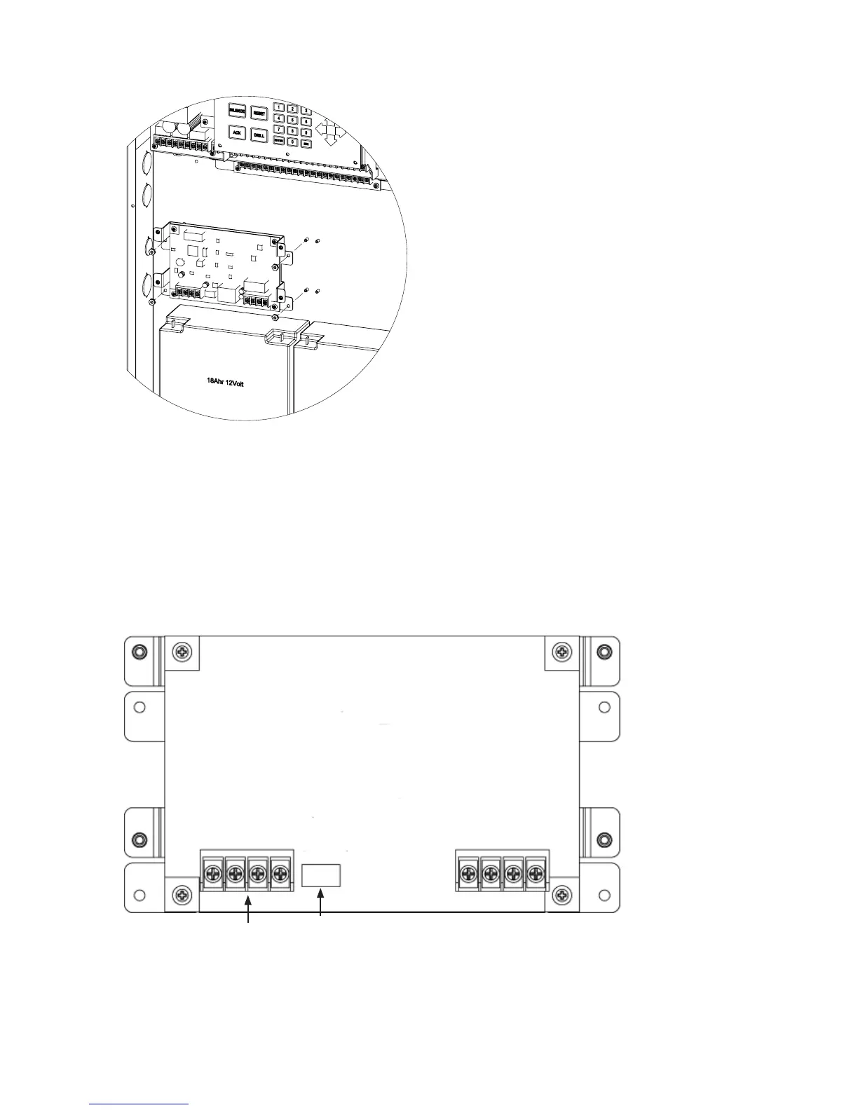
SLCE-127 Board Shown Installed in PFC-6800 CabinetFigure 54.
P-Link Circuit


Setting Addresses
dip switch S1 (as shown below
(Refer to the "P-Link Addresses" table shown earlier in this section for DIP switch programming.)
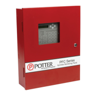
SLCE-127's Back Panel Showing P-Link Terminal & Dip Switch LocationsFigure 55.
DETAIL G
SCALE 1 : 2
DWG #602-17
DWG #608-28
-
+
B
A
S1
SLC OUT SLC RET
-
+
-
+
Dip Switch
P-Link
from Control
Panel

Table of Contents

Related product manuals