3-38
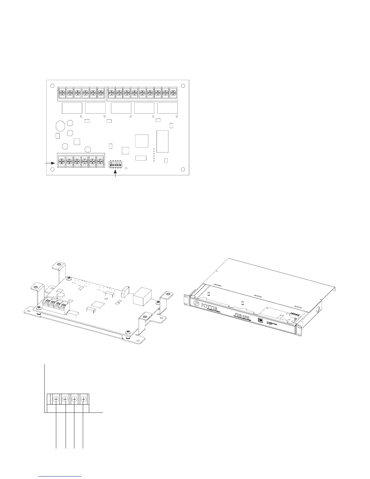
Setting Addresses
dip switch S1,
(Refer to the "P-Link Addresses" table shown earlier in this section for
DIP switch programming.)
Relay Board Back Panel View Showing Dip Switch LocationFigure 44.
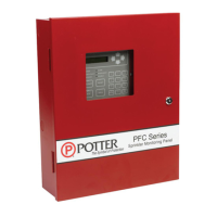
Fire Communications Bridge Installation (FCB-1000)
Note
FCB-1000 Bridge & FCB-1000RM Showing Rack MountFigure 45.
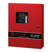
FCB-1000 Wiring to Control Panel ExampleFigure 46.
DWG #608-13
DWG #608-14
DWG #608-21
Dip Switches
P-Link
Connections
S1
DWG #608-26
P-Link
-
+ A B
P-Link from
control panel
Example:
Powered by
control panel