3-17
Section 3: Installation
Note: Instructions for installing the PSN-1000/PSN-1000(E) and/or the IP Dialer accessories are located in
Sections 6 and 7, respectively.
Signaling Line Circuit (SLC) Installation
.
SLC Wiring Requirements
MUST
•y must
•y
•y
•y
•y
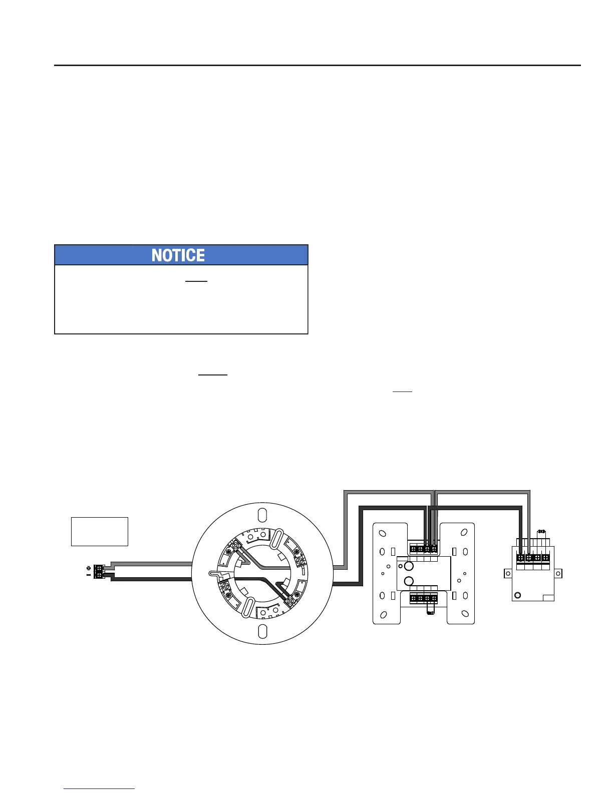
Class B, Style 4 Wiring Conguration
Example of SLC Wiring - Class B, Style 4Figure 7.
S- S+ C
NO
(NC)
Potter Electric Signal Company
Miniature Contact Module
Model No. MCM
Ser. No. xxxxxx
Document:
TN51314e date: XX.XX.2009
WARNING:
All Terminals are power limited
Address No.
SIGNALING
LISTED
L
U
FIRE ALARM EQUIPMENT
XXXX
Address No.
Potter Electric Signal Company
FIRE ALARM EQUIPMENT
XXXX
24- 24+ S- S+
B- B+ A- A+
Conventional Initiating Zone Module
Model No. CIZM-4
Ser. No. xxxxxx
Document: TN51313e date:XX.XX.2009
Compatibility Identier: INTE01
WARNING :
Power supply for terminals 24+ and 24- must
be power limited
All Terminals are power limited.
SIGNALING
LISTED
L
U
PFC-6000
Series
SLC Loop (Class B)
Terminal Connections
3
6
7
8
5.1kΩ
5.1kΩ
DWG # 593-7A
prior
Addressing SLC Devices”