3-37
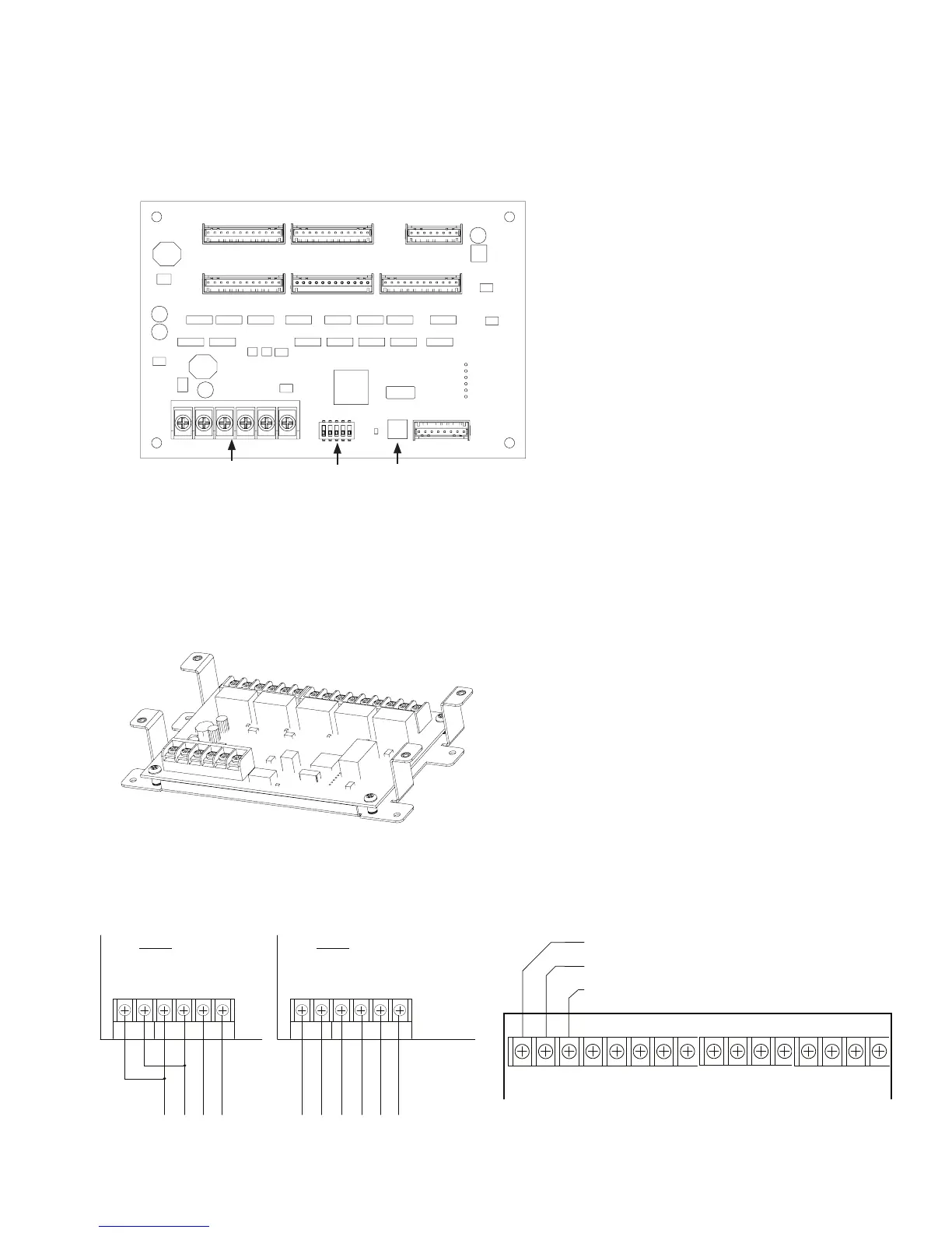
Setting Addresses
dip switch S1,
(Refer to the "P-Link Addresses" table shown earlier in this section for
DIP switch programming.)
DRV-50's Back Panel View Showing Dip Switch LocationFigure 41.
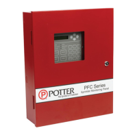
Relay Board Installation (RLY-5)
RLY-5 Board Showing Mounting BracketFigure 42.
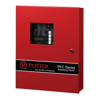
RLY-5 Wiring to Control Panel or Auxiliary Power Supply Examples & RLY-5 Showing Normally Open/Normally Closed ContactsFigure 43.
DWG #608-10
DWG #608-22
Dip Switch
P-Link
Connections
S1
RLY PWR P -Link
- + - + A B
P-Link from
control panel
Example:
Powered by
control panel
-Link
- + - + A B
P-Link from
control panel
Example:
Powered by
aux supply
Power from
auxiliary
supply
RLY PWR P
DWG #608-6
NC (Normally Closed)
C (Common)
NO (Normally Open)
NC C NO
RELAY 1
NC C NO
RELAY 2
NC C NO
RELAY 3
NC C NO
RELAY 4
NC C NO
RELAY 5
DWG #608-10C