[1] Heavy duty for IP66 models.
CODIFICATION EXAMPLES:
• SD305842F SD300, 58A, 400Vac three-phase, IP20 degree of protection,
EMC extended.
• SD301212 SD300, 12A, 230Vac single-phase, IP20 degree of protection.
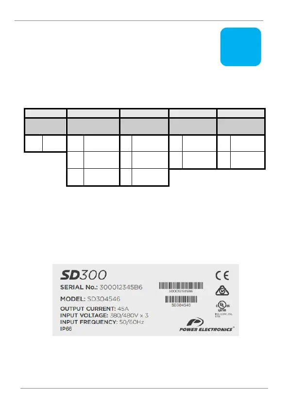
• The following figure shows an example of designation label:
Type designation label (located on lateral panel)