EasyManuals Logo

Power Electronics SD300 Series User Manual

Power Electronics SD300 Series
354 pages
To Next Page IconTo Next Page
To Previous Page IconTo Previous Page
Page #60 background imageLoading...
Page #60 background image
SD300
POWER ELECTRONICS
58
POWER CONNECTIONS
Power Connection and Wiring
CAUTION
The following installation recommendations are suitable for TN and TT
grids. For IT grids, consult Power Electronics. Otherwise, the equipment
could be damaged and the risk of injury heightened.
Any wiring or periodic inspections should be performed at least 10
minutes after disconnecting the input power. To remove the front cover,
first check that the DC Link red LED is off, then remove the metallic
cover and check with a multimeter the following:
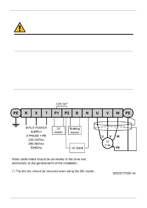
Measure between the output power busbars U, V, W and the cabinet
and check that the voltage is around 0V.
Measure that the DC link terminals +, - and chassis voltage are below
30VDC.
Otherwise, you may get an electric shock.
The user input and output busbars are labelled according to the following
diagram.
Power wiring connection

Table of Contents

Questions and Answers:

Question and Answer IconNeed help?

Do you have a question about the Power Electronics SD300 Series and is the answer not in the manual?

Power Electronics SD300 Series Specifications

General IconGeneral
BrandPower Electronics
ModelSD300 Series
CategoryInverter
LanguageEnglish

Related product manuals