EasyManuals Logo

Power Electronics SD300 Series User Manual

Power Electronics SD300 Series
354 pages
To Next Page IconTo Next Page
To Previous Page IconTo Previous Page
Page #214 background imageLoading...
Page #214 background image
SD300
POWER ELECTRONICS
212
DESCRIPTION OF PROGRAMMING PARAMETERS
Group 12: PLC Function UF
This group appears when AP.2 is set to 1 (Yes) or CM.95 is set to 2 (P2P
Master).
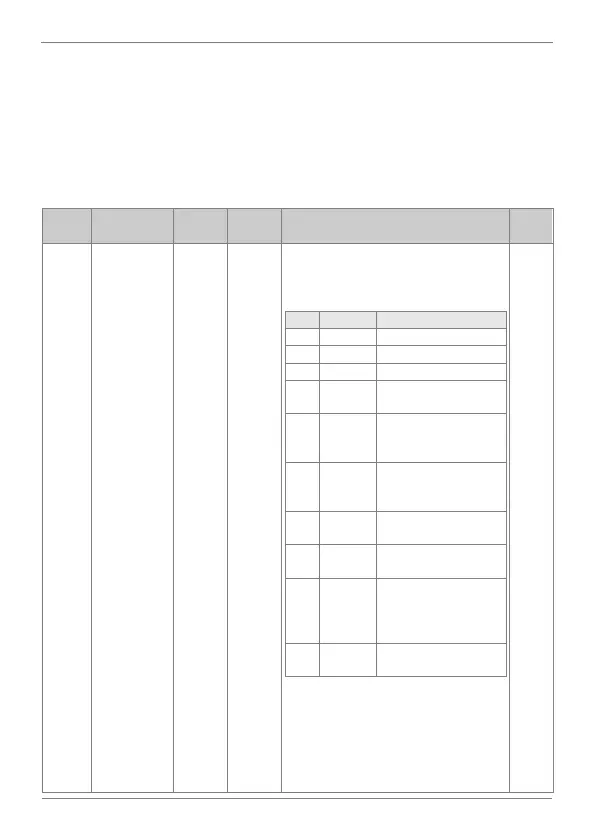
Set user defined functions for the 18 function blocks. If the function block
setting is invalid, the output of the User Output is -1. All outputs are read
only, and can be used with the user output link of the US group.
Screen
Description
Default
value
Range
Function
Set on
RUN
UF.1
PLC function 1
NOP
0 to 28
Choose the function to perform in the
function block, according to the following
table:
OPT.
DESCR.
FUNCTION
0
NOP
No operation
1
ADD
Addition, (A + B) + C
2
SUB
Subtraction, (A B) C
3
ADD SUB
Addition and subtraction
compound, (A + B) C
4
MIN
Smallest value of the
input values, MIN(A, B,
C).
5
MAX
Largest value of the
input values, MAX(A, B,
C).
6
ABS
Absolute value of the A
parameter, | A |
7
NEGATE
Negative value of the A
parameter, -( A ).
8
MPYDIV
Compound
multiplication and
division,
(A x B)/C.
9
REMAINDE
Remainder operation of
A and B, A % B
Note: Continues on the next page
NO

Table of Contents

Questions and Answers:

Question and Answer IconNeed help?

Do you have a question about the Power Electronics SD300 Series and is the answer not in the manual?

Power Electronics SD300 Series Specifications

General IconGeneral
BrandPower Electronics
ModelSD300 Series
CategoryInverter
LanguageEnglish

Related product manuals