EasyManuals Logo

Power Electronics SD300 Series User Manual

Power Electronics SD300 Series
354 pages
To Next Page IconTo Next Page
To Previous Page IconTo Previous Page
Page #175 background imageLoading...
Page #175 background image
POWER ELECTRONICS
DESCRIPTION OF PROGRAMMING PARAMETERS
173
Group 6: Outputs OU
Screen
Description
Default
value
Range
Function
Set on
RUN
OU.1
Analog output
1 mode
selection
Frequen
cy
0 to 15
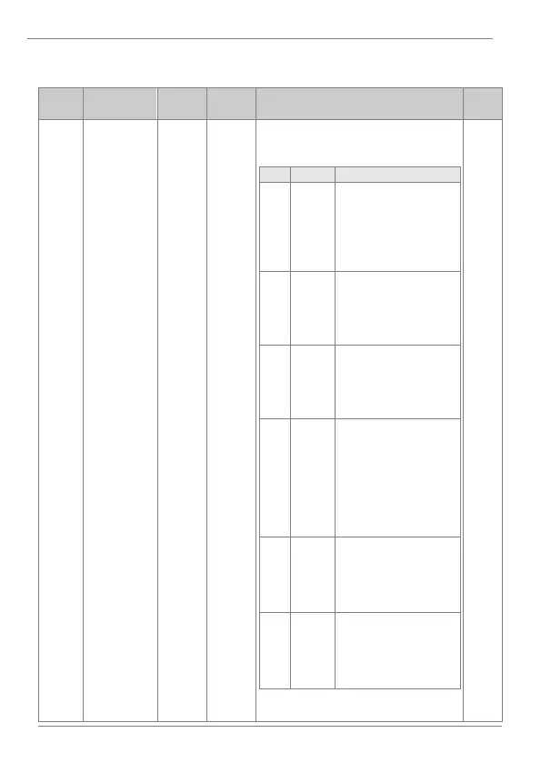
The analog output 1 is programmable
according to the following table:
OPT.
DESCR.
FUNCTION
0
Frequency
Proportional signal to the
motor speed. For the
maximum frequency
defined in M2.20,
analogue value will be
10V/20mA.
1
O/pCurr
Proportional signal to the
motor current. 10V/20mA
are generated when the
drive rated current is at
200%.
2
O/pVolt
Proportional signal to the
motor voltage. For the
voltage value defined in
bA.15, analogue value will
be 10V/20mA.
3
DCLink
V
Proportional signal to the
bus DC voltage. The
analogue output is
10V/20mA when the DC
voltage is 410Vdc for
220Vac drives and
820Vdc for 400Vac
drives.
4
Torque
Proportional signal to the
generated torque.
Outputs 10V/20mA at
250% of motor rated
torque.
5
O /
pPower
Proportional signal to the
output power. 10V/20mA
are generated operating
200% of the nominal
power.
Note: Continues on the next page.
YES

Table of Contents

Questions and Answers:

Question and Answer IconNeed help?

Do you have a question about the Power Electronics SD300 Series and is the answer not in the manual?

Power Electronics SD300 Series Specifications

General IconGeneral
BrandPower Electronics
ModelSD300 Series
CategoryInverter
LanguageEnglish

Related product manuals