DESCRIPTION OF PROGRAMMING PARAMETERS
Set drive operating frequency for the
maximum voltage input of the analog input.
Voltage analog input 1 (V1) visualization.
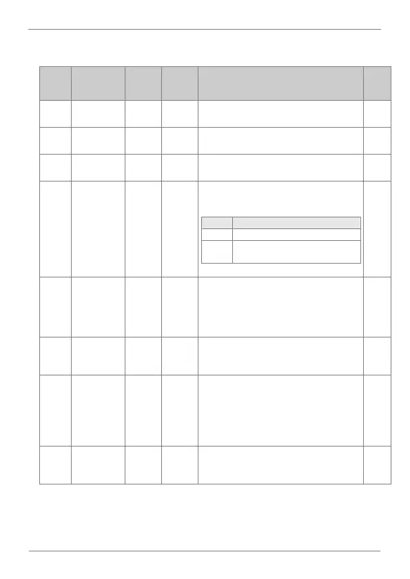
This parameter allows setting the operation
directions of the drive:
Unipolar (forward operation)
Bipolar (forward and reverse
operation directions)
Low Pass Filter for V1. Allows setting the time
response to a change produced in the speed
reference, to reduce the speed fluctuation due
to unstable signs or noise. Thus, the response
becomes slower.
Define the minimum voltage for the analog
input 1 according to the connected sensor
characteristics
Set the speed reference corresponding to the
analog input 1 minimum negative range. It
corresponds to the minimum voltage level set
in In.12. It is configured to introduce the speed
reference through the AI. The value is a
percentage of the frequency set in In.1.
Define the maximum voltage for the analog
input 1, according to the connected sensor
characteristics.