Testing the BLU wire connection prior to VAC configuration
(Not applicable for JPT, P-Plug and VDI cable installations)
Per the installation instructions, installers need to measure voltage changes for connection points of the inputs required.
The “BLU” wire is used for motion sense (drive motor on electric vehicles and in gear on internal combustion vehicles).
There are 2 modes for motion configuration, “V(avg)” and “V(mix/max).
V(avg) uses the average voltage reading, typically used for DC voltage and AC square wave voltage signals.
V(min/max) uses the peak-to-peak voltage reading, typically used for AC sine wave voltage signals.
To be sure the BLU wire connection will work for the Install Wizard, there is a MotionTest screen available to see the VAC
results in either of these modes. Connect the BLU wire using clip-leads, or permanently and then:
1. Log into the vehicle.
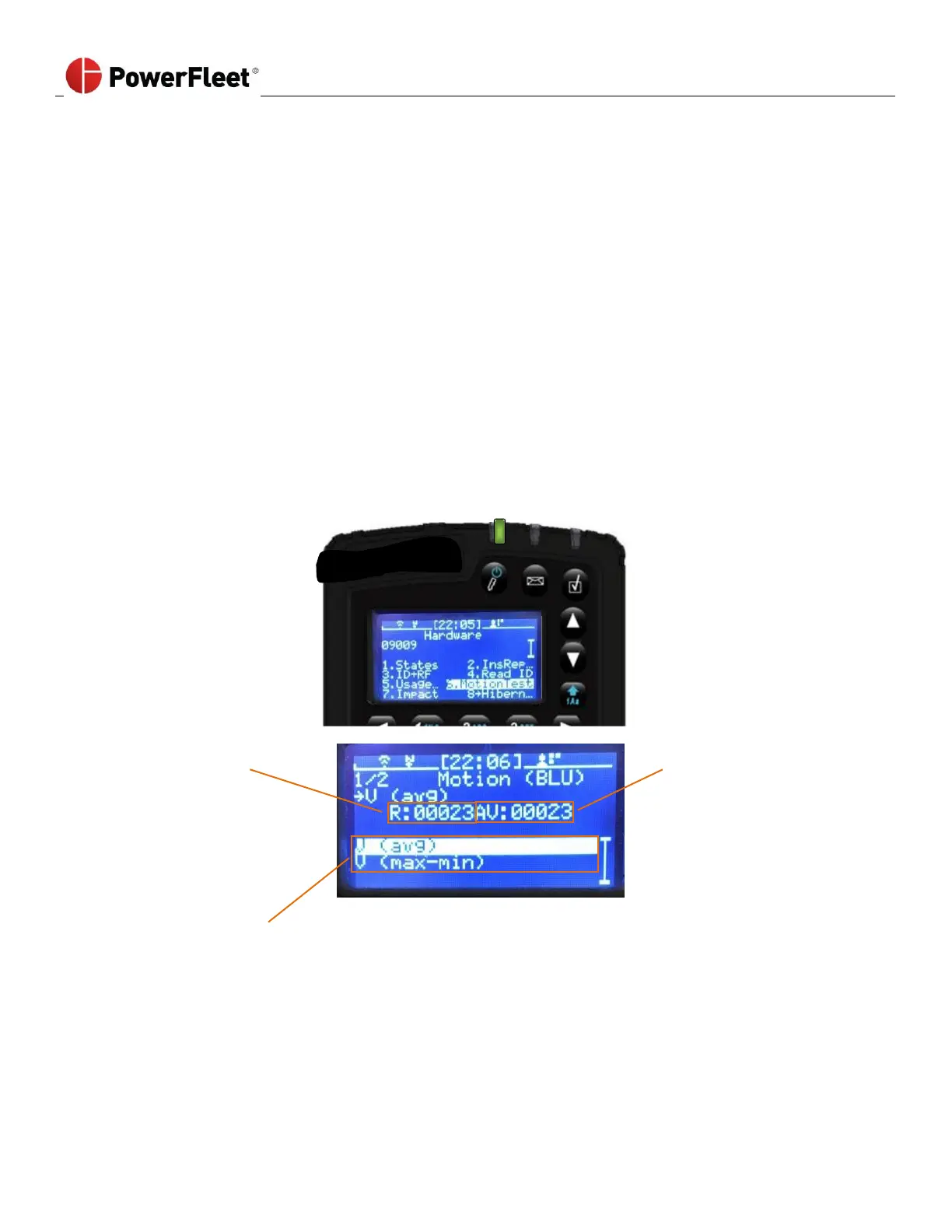
2. On the first menu screen, select HARDWARE.
3. On the “Hardware” sub-menu, select MOTIONTEST.
Use the up and down arrows
To switch between modes
4. Select the desired mode
5. Note the idle (not driving) value of AV with the key off
6. Note the idle (not driving) value of AV with the key on.
7. Drive and note the value of AV (needs to be more than 10 points different than the non-driving values)
8. If not, switch modes and repeat steps 5 through 7.
9. If neither mode provides the desired results, you need to find a different connection point