PowerFleet
®
VAC4 and VAC4S Hardware User’s Guide
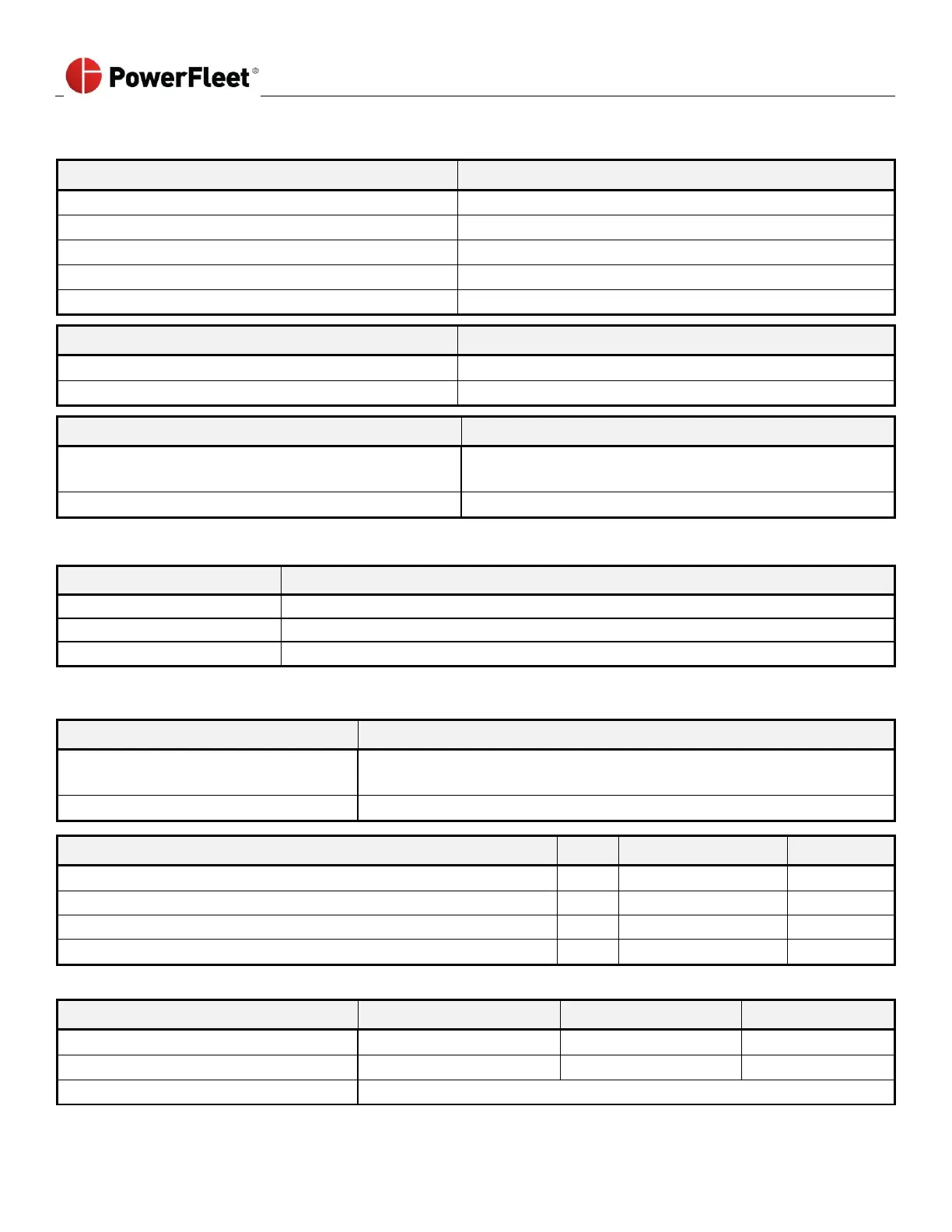
User Interface Specifications
Membrane/polyester; 20 keys
DFSTN, black/white; 132 x 64 pixels
4, integrated, 270
o
viewable from 50’
External/Bottom edge mount
HID only (VAC4) or
Multi-Prox (50+ protocols; 125 KHZ or 13.65 MHz – VAC4S)
Proximity Reader Location
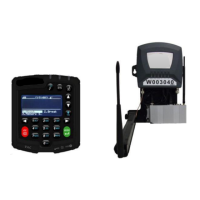
Electrical considerations
Isolation from chassis required (and provided)
2 x M6 screws or bolts (supplied)
2 x ¼” dia. holes for bracket, 1x 1.25” dia. round hole for cable
Electric vehicle connection
Avg: average DC or ‘AC’ square-wave duty-cycle monitoring (BLU Wire)
Min/Max: peak-to-peak (BLU Wire)
Internal Combustion vehicle connection
Engine on and in-gear (BRN and BLU wires)
Motion, Lift motor, Seat/Deadman Sense Criteria
Voltage Range (Electric vehicle)
Voltage Differential – Idle/Motion (Electric vehicle; BLU wire)
Voltage Range (Internal combustion vehicle)
Voltage Differential Idle/Motion (IC vehicle; BRN and BLU wires)
†Voltage differential between motion state and idle state must be at least 1.0 volt
Auto-configuring; manual threshold settings not required