PowerFleet
®
VAC4 and VAC4S Hardware User’s Guide
SECTION 1: SYSTEM OVERVIEW
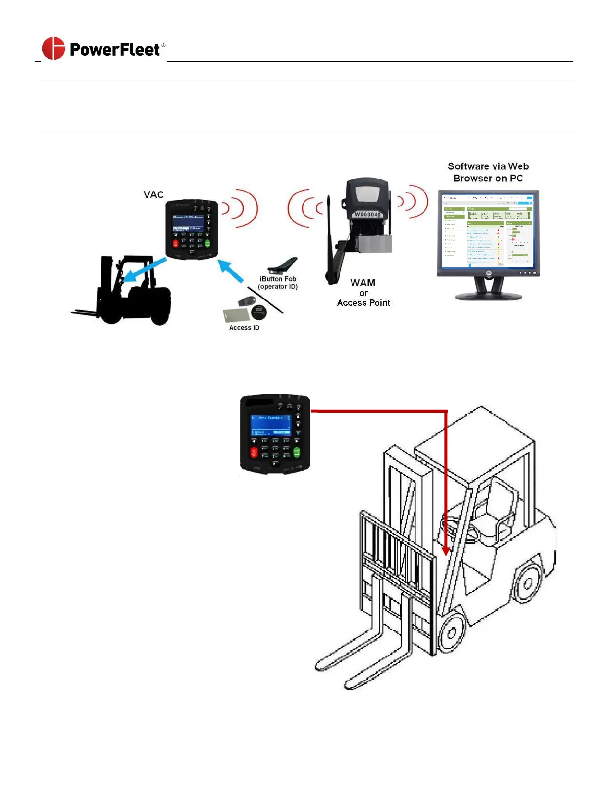
PowerFleet Enterprise System Diagram
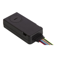
Placement of a VAC on a vehicle
• VAC must be mounted on the
vehicle where it can be
accessed by the operator
without interfering with any
vehicle operation.
• VAC interfaces with the
vehicle for power, ignition/
access control, and usage
monitoring using an 18-foot
cable harness.
• VAC interfaces with operators
through Access ID readers,
LEDs, a keypad, and a backlit
LCD display.
• VAC communicates
automatically with remotely
hosted software via a WAM
or Access Point, but operates
seamlessly, even when not in
coverage range.