129
4. Disconnect the Ethernet cable and move it out of the way if necessary.
5. Remove the 25 pin Dsub blank cover plate from the connector panel by removing the M3 BHCS.
These screws are retained by M3 nylon insert hex nuts on the back of the front connector panel.
6. Remove all 4 address jumpers on the GIO board J8-J11, see picture below.
7. Install the GIO board with 4 M3 X 10 SHCS on the rear surface of the Z column as shown below.
8. Install the 10 conductor RS485 jumper cable from the GIO board to the connector panel board.
9. Attach the 25 pin Dsub connector pigtail to the connector panel with the 4-40 standoff kit and plug
the 26pin connector into the GIO board. Be careful to fold the harness to the D sub as shown.
10. Reconnect the Ethernet Cable.
11. Replace the covers.
12. Set value 8 in Data ID 151 to “GIO_8”, so that this ID reads “<Controller Serial No>”,
“GSB_1”, “”,“”,“”,”“”,“”,GIO_8” This parameter may be found in Setup/Parameter
Database/Controller/System ID.
13. GIO signals may then be checked under Control Panels/Remote IO/Network Node 8.
To install the GIO Board in a robot with a Linear Axis the user must:
1. Slide the carriage of the Linear Axis to one end of travel.
2. Remove the top cover from the Linear Axis by removing 4 M4 X 30 SHCS from the end caps. It
may be necessary to loosen the two bottom screws on the connector end cap to provide
clearance to remove the cover.
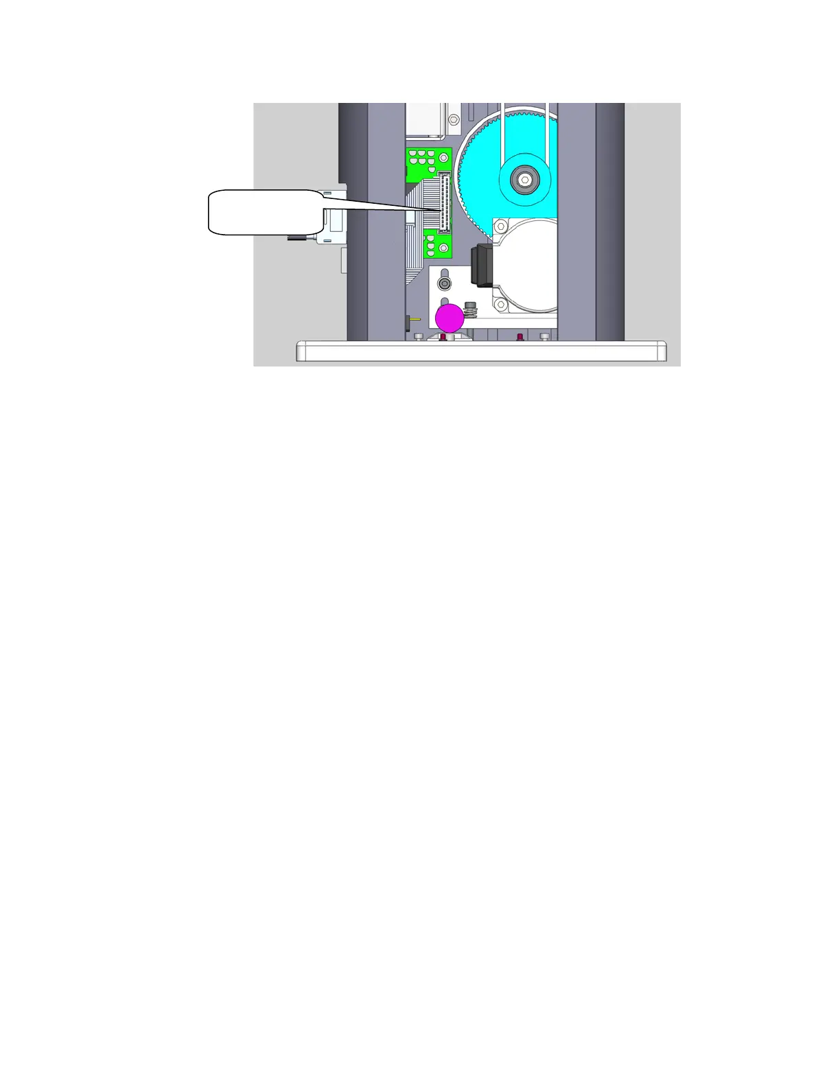
3. Remove all 4 address jumpers on the GIO board J7-J10, see picture below.
25conductor
cable to here