PreciseFlex_Robot
130
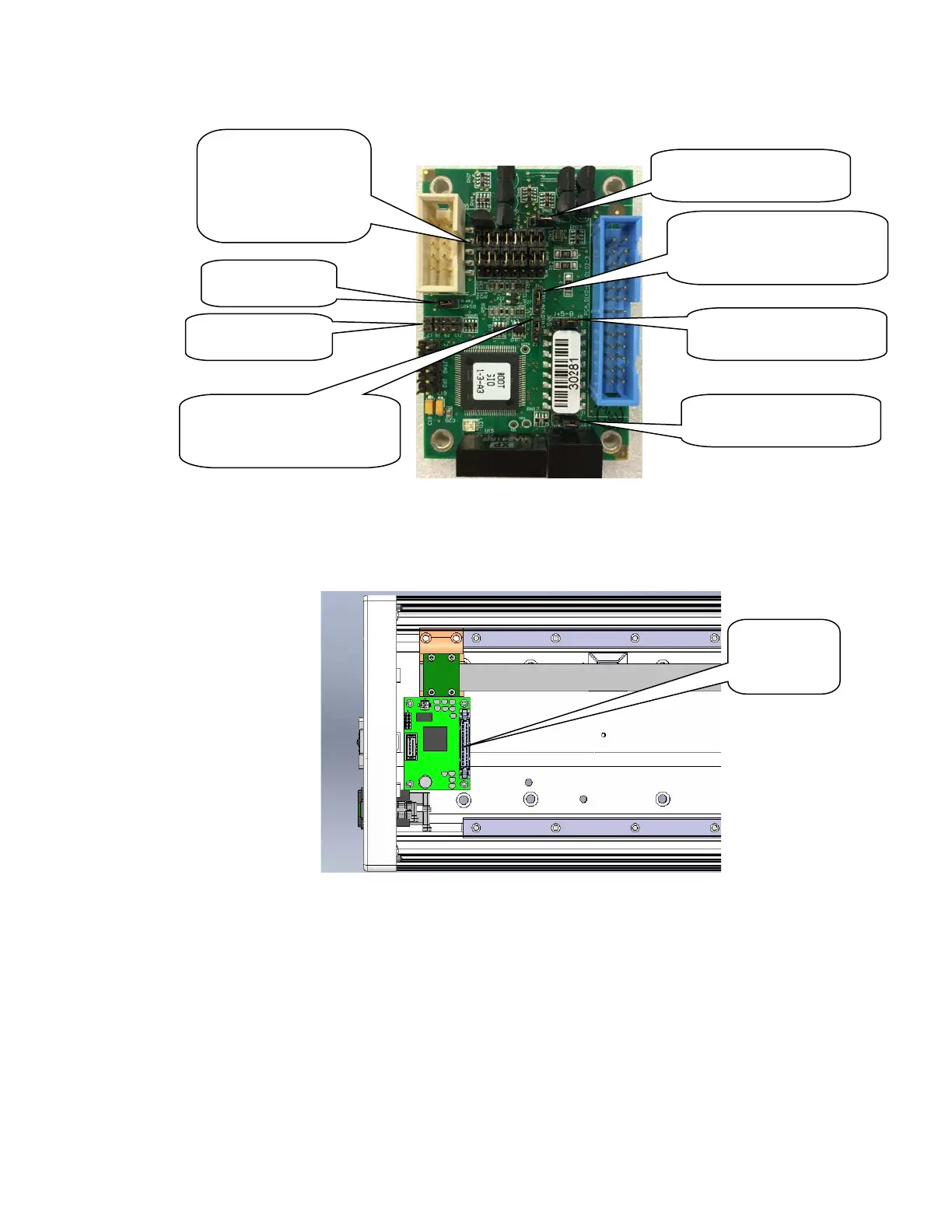
4. Install the GIO Board in the linear axis using 4 M3 X 10 SHCS and lockwashers.
5. Remove the termination resistor from the 10 pin connector plug attached by 4 wires to the 9 pin
Dsub Pendant connector and plug the 10 pin connector into the GIO board.
6. Install the GIO output pigtail by plugging the 26 pin connector into to the GIO board and attaching
the 25 pin Dsub connector to the end cap with the 4-40 standoffs provided. Make an accordion
fold with the extra ribbon cable and tie wrap to hold the fold down over the GIO board.
7. Replace the covers.
8. Set value 8 in Data ID 151 to “GIO_8”, so that this ID reads “<Controller Serial No>”,
“GSB_1”, “”,“”,“”,”“”,“”,GIO_8” This parameter may be found in Setup/Parameter
Database/Controller/System ID.
9. GIO signals may then be checked under Control Panels/Remote IO/Servo Node 8.
GIO Board
Remove J7, J8,
Install J6
Digital Outputs 1-8
Default Position is
sinking. Moving
both jumpers up 1
pin for sourcing
J3: Digital Inputs 1-4
sourcing position
J4: Digital Inputs 5-8
sourcing position
J5: Digital Inputs 19-12
sourcing position
J1: Digital/Analog Input 11
Connect Pins 1&2 for
digital input
J2: Digital/Analog Input 12
Connect Pins 1&2 for
digital input