Section 06: ELECTRICAL
PA1593
28
must be displayed. If this is the case, press
ESCape button repeatedly to acknowledge
the higher priority messages.
o Check the Diagnostics menu of the Driver
Information Display (DID). Select Fault
Diagnostics and Electrical System. Verify
the fault message to be certain the module is
reprogrammed. If the module is not
reprogrammed, the message “Axx Not
Responding” appears where Axx is the
module number (Ex: A41, A42…etc).
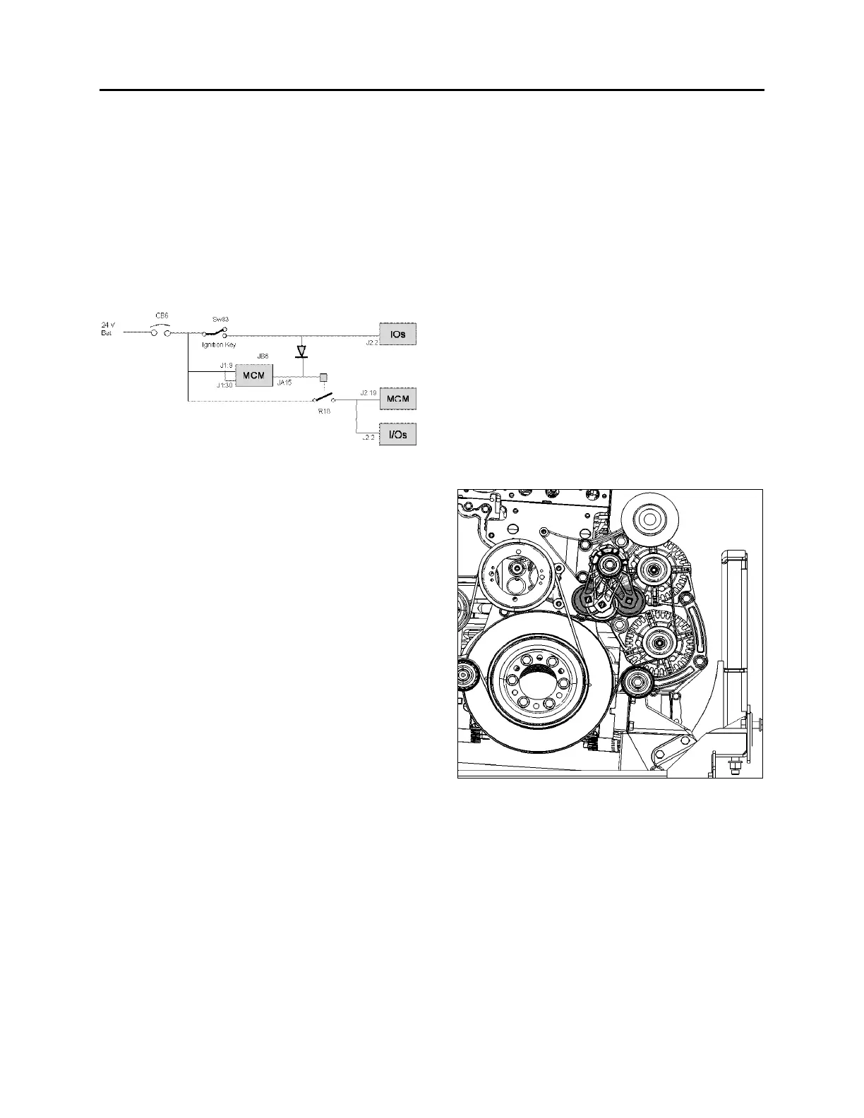
JB6 is a wake-up pin
JA15 output remains active for 15 minutes after
JB6 is inactive
To initiate reprogramming:
o Switch SW83 (ignition key) closed, providing
24-volt on JB6, I/O modules and R18. All
modules get power.
o CB6 is tripped and reset which is forcing
MCM reboot.
o When resetting CB6, all modules gets power,
MCM goes into Start Mode. I/O modules
needing new program will request
reprogramming to MCM while in Start Mode.
4.13.2 Replacing The MCM Module
o Set the ignition key to the ON position and
leave it in that position at all time while
performing this procedure.
o On rear electrical junction panel, trip circuit
breaker CB6.
o Replace the module.
o Reset circuit breaker CB6.
o The vehicle specific program needs to be
uploaded in the MCM. A laptop computer
equipped with VPG (Vehicle Program
Generator) software must be connected to
the DB9 (9-pin) connector (identified C226)
found in the electrical harness near the
MCM.
Please contact your Prevost
Service Representative.
5. BOSCH ALTERNATORS
Two 28 volt 120A, self regulated, belt driven, air-
cooled HD 10 BOSCH alternators are used in
the 24 volt electrical system.
If the alternators needed to be removed, reinstall
as follows. Refer to figure 22 for installation and
to figure 23 for tightening specifications:
1. If necessary, tighten screws (6) fixing
alternators support assembly onto engine
(1, figure 23). Torque tighten to 43 Lb-Ft,
use some Loctite 243 blue (680038) onto
the threads. Also tighten screw (1) fixing belt
tensioner onto alternators support assembly
(1, figure 23). Torque tighten to 43 Lb-Ft,
use some Loctite 243 blue (680038) onto
the threads.
2. If removed, reinstall screw (1) fixing
alternators support assembly onto engine
(2, figure 23). Torque tighten to 22 Lb-Ft,
use some Loctite 243 blue (680038) onto
the threads.
FIGURE 22: ALTERNATORS DRIVE BELT
3. Mount the A/C compressor idler pulley onto
alternators support assembly (3, figure 23).
Torque tighten to 150 Lb-Ft, use some
Loctite 243 blue (680038) onto the threads.
4. Install alternators arched support loosely
onto engine. If removed, install alternators
idler pulley (4, figure 23) onto alternators
arched support, torque tighten to 43 Lb-Ft.