Section 03: FUEL SYSTEM
PA1593
11
5.2 AIR CLEANER SERVICING
Stop the engine, open the R.H. side engine
compartment door, and loosen the wing nut
retaining the air cleaner element to the air
cleaner. Remove the element by pulling on the
handle in the center of the air cleaner element.
Install cleaner element as follows:
1. Inspect the gasket-sealing surface inside the
air cleaner. It must be smooth, flat and clean;
2. Install the air cleaner element;
3. Make sure that the element seals securely;
4. Inspect element cover gasket and replace if
necessary.
Whenever it becomes necessary to remove the
air cleaner assembly (dry type) for maintenance
or other repair in this area, great care should be
taken when installing air cleaner assembly.
The pre-filter should be installed snugly in the air
duct and clamped tightly to the air cleaner inlet
to prevent any dust infiltration into the air
cleaner.
5.3 GENERAL RECOMMENDATIONS
The following maintenance procedures will
ensure efficient air cleaner operation:
1. Keep the air cleaner housing tight on the air
intake pipe;
2. Make sure the correct filters are used for
replacement;
3. Keep the air cleaner properly assembled so
the joints are air-tight;
4. Immediately repair any damage to the air
cleaner or related parts;
5. Inspect, clean or replace the air cleaner or
elements as operating conditions warrant.
Whenever an element has been removed
from the air cleaner housing the inside
surface of the housing must be cleaned with
a soft clean cloth;
6. Periodically inspect the entire system. Dust-
laden air can pass through an almost
invisible crack or opening which may
eventually cause damage to an engine;
7. Never operate the engine without an element
in the air cleaner assembly;
CAUTION
Do not ignore the Warning given by the air
restriction indicator. This could result in
serious engine damage.
8. Store new elements in a closed area free
from dust and possible damage.
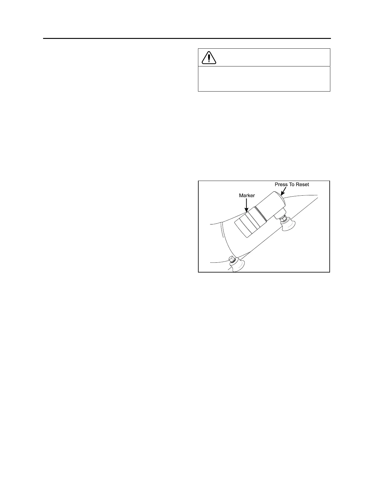
5.4 AIR CLEANER RESTRICTION INDICATOR
A resettable restriction indicator may be installed
on the engine air-intake duct, clearly visible from
the rear engine compartment. The indicator
monitors the vacuum level between the air filter
and the engine. A red marker is displayed when
the air filter is clogged and must be replaced.
Reset by pressing on the indicator's extremity.
FIGURE 10: RESTRICTION INDICATOR 01052
6. FUEL PEDAL
The EFPA (Electronic Foot Pedal Assembly)
connects the accelerator pedal to a
potentiometer (a device that sends an electrical
signal to the ECM, which varies in voltage,
depending on how far down the pedal is
depressed). The EFPA is installed in the space
normally occupied by a mechanical foot pedal. It
has maximum and minimum stops that are built
into the unit during manufacturing.
6.1 FUEL PEDAL ADJUSTMENT
The EFPA contains a throttle position sensor
that varies the electrical signal sent to the ECM.
The sensor must be adjusted whenever an
EFPA is serviced. In addition, the sensor should
be adjusted any time codes 21 and 22 are
flashed.