Section 18: BODY
PA1593
17
NOTE
Position the ball cup halves so the joint
between them lies on the centerline of the
arm. Ensure that the setscrews are not on the
joint between the cup halves.
Replacement of Mirror Glass
Remove the broken glass.
Position new glass in mirror head and press to
lock the Velcro in place.
Remote Controlled Rear View Mirrors
The remote controlled external rear view mirrors
attach to support arms using a pivot collar
secured by setscrews. Loosening the setscrews
allows the whole head assembly to turn on the
support arm for initial adjustment. A mounting
bolt and washer hold the arm support to the
mounting bracket. The arm support can be
moved to position the mirror head into or away
from the coach body.
o Mirror Control
The remote control pointer knob(s) for the
mirrors is (are) mounted on the L.H. side control
panel. The harness to the mirror head runs
through the arm support. The remote motor is
mounted to the mirror head behind the mirror
glass.
Turn pointer knob to the left for mirror head
adjustments and to the right for convex mirror
adjustment, then push down on either of the
button’s (4) sides to adjust the selected mirror
viewing angle.
o Disassembly
At end of mirror arm, loosen the setscrews to
relieve tension on the ball stud. Remove the ball
stud. Remove the ball stud from the arm and
gently pull the harness out until the connector is
exposed.
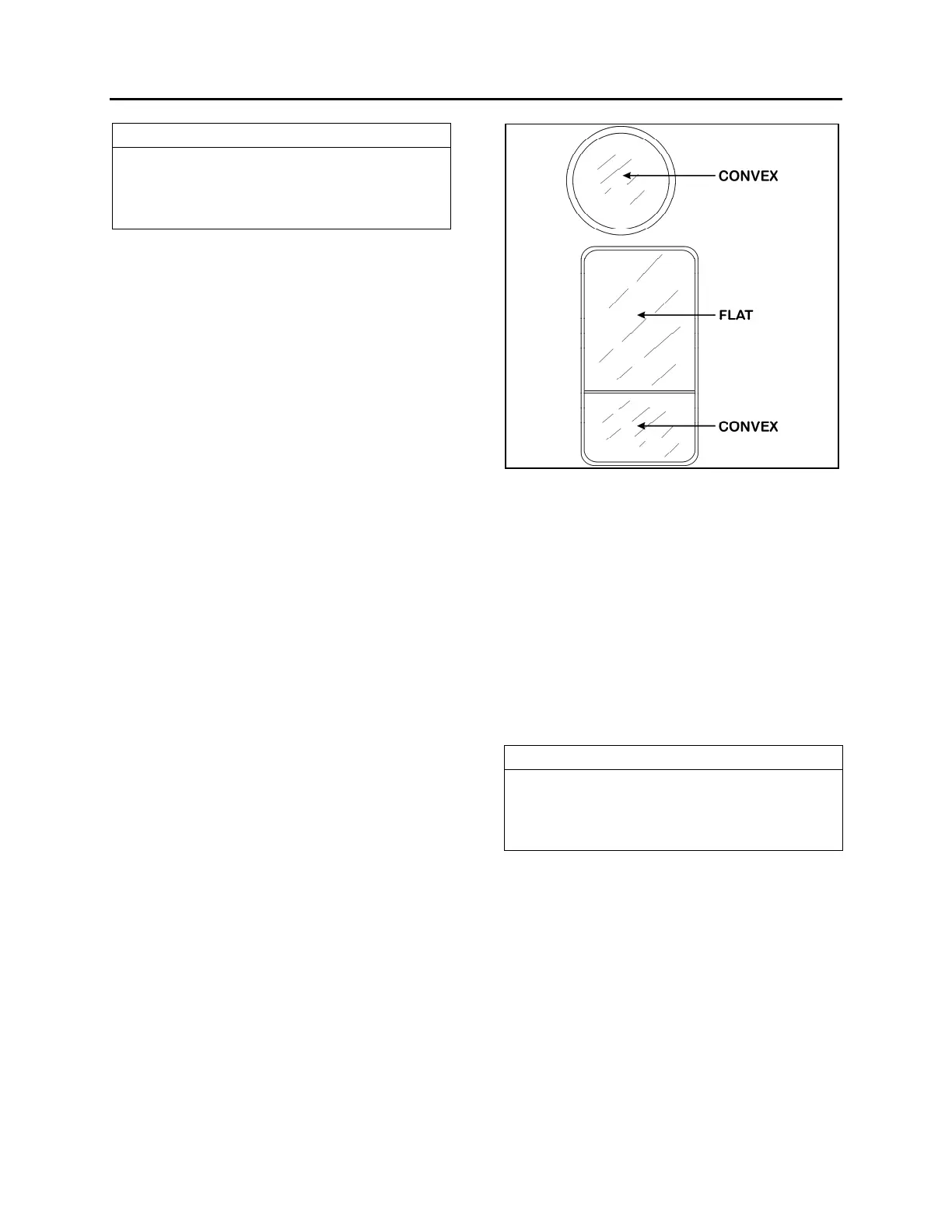
FIGURE 13: OUTSIDE REAR-VIEW MIRROR
Remove the four screws fastening the mirror
arm base to the coach. Slide the harness free of
the mirror arm base.
o Assembly
Attach a stiff wire (snake) to the end of the
harness and insert the wire through the mirror
arm base and arm, gently pull the harness
through the arm and disconnect the "snake".
Connect the mirror head harness. Insert the
harness connector back into the mirror arm.
Insert the ball stud into the mirror arm and
tighten the socket setscrews.
NOTE
Position the ball cup halves so the joint
between them lies on the centerline of the
arm. Ensure that the setscrews are not on the
joint between the cup halves.
o Convex & Flat Mirror Removal
The mirror glass assembly is mounted to the
control mechanism or to mirror base with Velcro
strips. Remove the mirror glass by gently pulling
the lens to release the Velcro. Disconnect the
heater grid at the two connectors.
Connect the connectors of the new mirror’s grid
to the harness. Install the lens by positioning the
lens in the mirror frame and pressing to lock the
Velcro in place.