Section 06: ELECTRICAL
PA1593
35
The rear clearance and identification lights are
red and the front ones are amber.
The amber marker lights are mounted along the
sides of vehicle.
The side marker light is a sealed unit (LED) and
should be replaced as an assembly in
accordance with the following procedure:
1. Unscrew both “Phillips” light screws, and
then remove the light assembly.
2. Position the new light assembly and install
the “Phillips” screws.
10.4.1 Clearance and Identification Light
Removal and Replacement
The clearance and identification light are sealed
units (LED) and can be replaced in accordance
with the following procedure:
1. Unscrew both “Phillips” light screws, and
then remove the light assembly.
2. Position the new light assembly, and then
install the “Phillips” screws.
11. INTERIOR LIGHTING EQUIPEMENT
11.1 CONTROL PANEL LIGHTING
The instrument gauges and switches mounted
on all control panels are energized whenever
the exterior light switch is pushed to the first
position. A control dimmer located on the
dashboard is used to vary the brightness of the
panel gauges, switches and indicator lights.
The gauge lights, panel lights, switch lights and
indicator lights have a different bulb
arrangement. Thus, the procedure to change a
defective bulb can vary according to the
application.
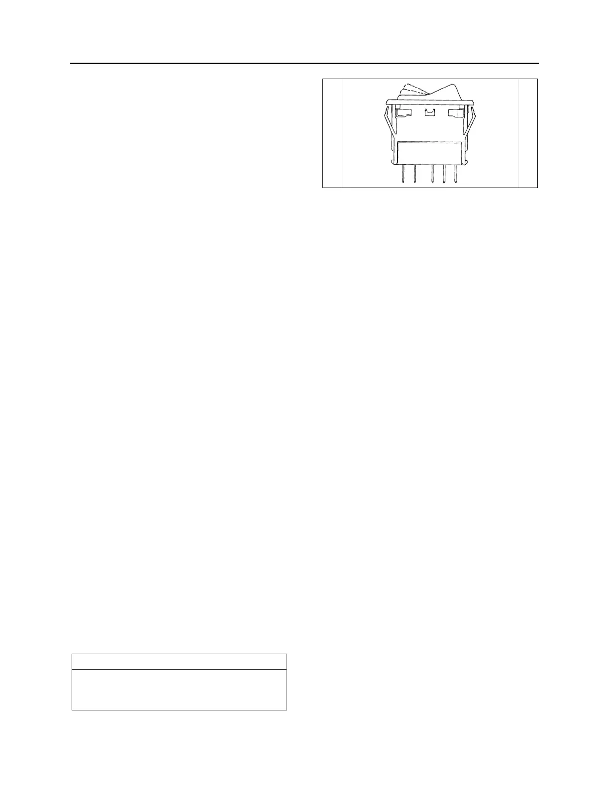
11.1.1 Switch Lighting
1. Slightly pull the switch with a defective LED
away from the control panel.
2. Disconnect the electric cable from the
switch.
3. To install a new switch, reverse the
procedure (Fig. 35).
NOTE
Switches are lighted by the use of LED. When
lighting on a switch fails, replace defective
switch as a unit.
FIGURE 35: SWITCH 06321
11.1.2 Telltale Light Replacement
Telltale module is non-serviceable and must be
replaced as a unit.
1. Unscrew and remove the top dashboard
panel.
2. Remove the telltale back wire electric
connectors.
3. Unscrew and remove the telltale module.
4. To replace the telltale module, reverse the
procedure.
11.1.3 Gauge Light Bulb Replacement
1. For any gauge light bulb replacement, the
dashboard panel must be removed in order
to have access to the rear of gauges.
2. Remove bulb socket from the gauge, turn
the defective bulb counterclockwise and pull
it out of the gauge.
3. Push a new bulb and socket ASM and turn
clockwise to lock in place.
4. Replace the rear dashboard housing.
11.2 STEPWELL LIGHTS
Two Stepwell lights are illuminated when the
door opening system is activated.
11.2.1 Bulb Removal and Replacement
Proceed as follows to replace a defective bulb:
1. Unscrew the two Phillips-head screws
retaining the lens to the wall, and remove it.
2. With the light lens removed, pull bulb from
the lamp while applying lateral pressure.
3. Install the new bulb into the lamp.
4. Position the light lens and install it.



 To Next Page