Section 16: SUSPENSION
PA1593
22
When the desired height is obtained, tighten
clamp.
Rear air spring clearance
1. With the vehicle at normal operating air
pressure [100 - 125 psi (689 - 860 kPa)],
measure air spring clearance. This
clearance should be 11 ½ ± ¼" (292 ± 6
mm).
NOTE
The measurement should be taken from
underneath the upper air spring support on
subframe to top of the lower air spring support
on axle (refer to figure 24 for more details).
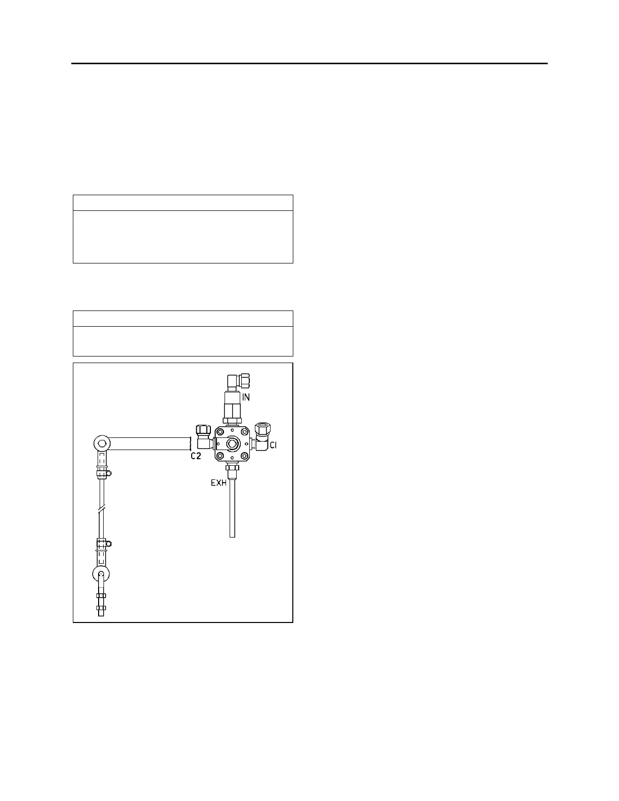
2. Loosen the clamp on the height control
valve rubber coupling and bring it up or
down (Fig. 26).
NOTE
Allow suspension to stabilize before taking
reading.
FIGURE 26: REAR HEIGHT CONTROL VALVE 16093
When the desired height is obtained, tighten
clamp.
5. HEIGHT CONTROL VALVE
The height control valves automatically add air
to, or release air from air springs to maintain
constant suspension height regardless of load,
or load distribution. Each valve adjusts
independently according to the following
conditions:
Loading Position
As the load increases and lowers the vehicle
body, the overtravel lever commands the height
control valve to add air to air springs.
Neutral Position
When vehicle body reaches the normal ride
height, the height control valve overtravel lever
reaches the "neutral" position and keeps both
the supply and exhaust ports closed to ensure
normal ride height is maintained. This condition
remains static until the vehicle load is altered.
Unloading Position
As the load decreases and raises the vehicle
body, the overtravel lever commands the height
control valve to release air from air springs.
5.1 MAINTENANCE
The height control valve requires no periodic
maintenance. Height control valve linkage
operates on rubber bushings and no lubrication
should be attempted at this location. Inspect the
valve for loose joints, air leaks and worn
bushings.
5.2 REMOVAL AND INSTALLATION
Before disconnecting a height control valve air
line, securely support the vehicle by its jacking
points on the body, and place safety supports
underneath body. Refer to paragraph "16.
Vehicle Jacking Points" in Section 18, "Body".
1. Exhaust air from air system by opening all
air tank drain cocks. Remove height control
valves.
2. Disconnect overtravel lever from link and
pull down lever to exhaust remaining air
from air springs.
3. Disconnect air supply and delivery lines
from the height control valve. Cover line
ends with tape to prevent entry of foreign
matter.
4. Remove the nuts retaining the height control
valve to the mounting bracket, then remove
valve assembly.