Section 05: COOLING SYSTEM
14 X3-45 Commuter PA1593 DOB 2400-2489 Section 05 Updated Sept.2016
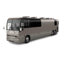
FIGURE 19: REMOVING FASTENERS
20. Remove upper fan drive support bracket
from the upper section of the radiator.
FIGURE 20: REMOVING UPPER FAN DRIVE SUPPORT
BRACKET
21. With assistance, remove fan drive and drive
frame from radiator.
22. Remove fan shroud from radiator.
FIGURE 21: REMOVING FAN SHROUD FROM RADIATOR
23. Reverse removal procedure to reinstall
radiator assembly.
11. CHARGE AIR COOLER LEAKAGE
Spec for CAC acceptable leakage:
“The CAC is considered acceptable if it can hold
30 psi (206 kpa) gauge pressure with less than
5 psi (34.5 kpa) loss in 15 seconds after turning
off the hand valve.”
NOTE
This spec does not apply if there is any
evidence that the leak was caused by a
foreign object impact.
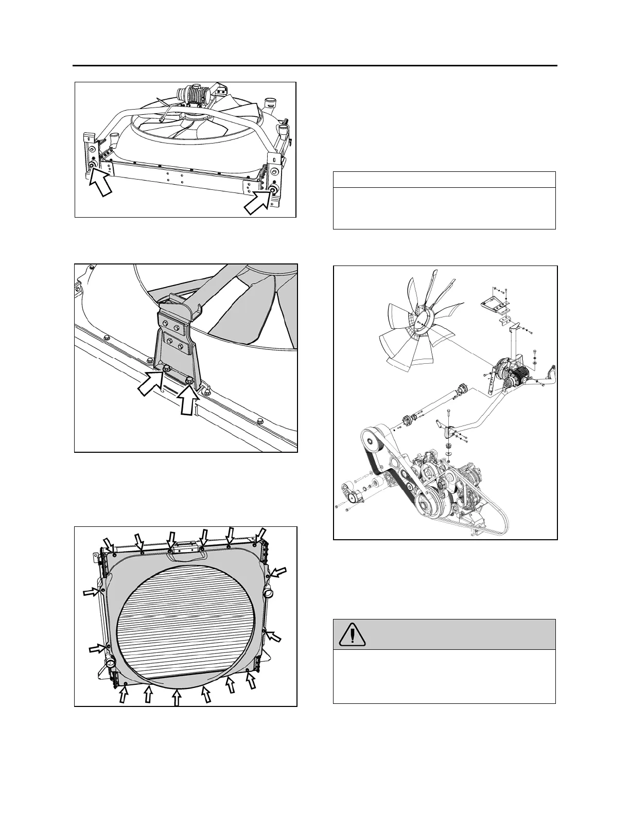
12. COOLING FAN DRIVE MECHANISM
FIGURE 22: COOLING FAN DRIVE MECHANISM
12.1 DRIVE PULLEY AND UNIVERSAL JOINT
SHAFT
To disconnect the universal shaft, proceed as
follow:
WARNING
Turn the ignition switch to the OFF position
and set starter selector switch to the OFF
position to prevent accidental starting of the
engine.