Section 12: BRAKE AND AIR SYSTEM
Section 12 Updated Sept. 2015 X3-45 Commuter PA1593 DOB 2400-2489 13
FIGURE 19: SR-7 12206
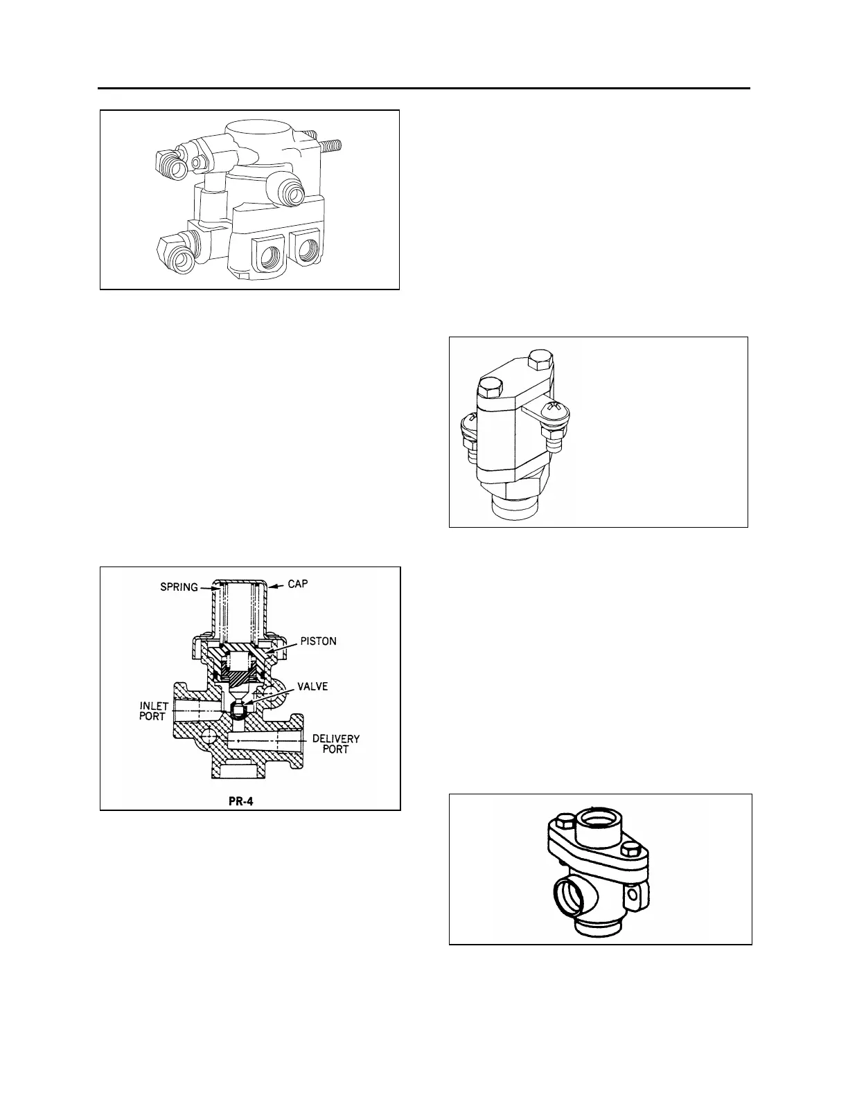
21. PRESSURE PROTECTION VALVE (PR-4)
Maintenance and repair information on the
pressure protection valve is supplied in the
applicable booklet annexed to this section under
reference number SD-03-2010.
The air system includes two pressure protection
valves (Fig. 20). One valve is installed on the
manifold block, and insures at all times a
minimum pressure of 70 psi (482 kPa) in the
suspension air system in the event that a
pressure drop occurs in either the suspension air
system or accessory air system. This valve is
located in the front service compartment beside
the air filter.
FIGURE 20: PR-4 12174
The other valve is installed on the accessory air
tank, and insures a minimum pressure of 70 psi
(482 kPa) in the accessory air system in the
event that a pressure drop occurs in either the
suspension air system or braking air system
(refer to Fig. 1 for accessory air tank location).
22. LOW PRESSURE INDICATOR (LP-3)
Maintenance and repair information on the low
pressure indicators is supplied in the applicable
booklet annexed to this section under reference
number SD-06-1600.
The air system includes two low pressure
switches (Fig. 21), both located on the
pneumatic accessory panel in the front service
compartment. One serves for the parking brake
signal, its pressure setting is 66 ± 6 psi (455 ± 40
kPa). The remaining pressure switch monitors
the parking brake telltale panel indicator; its
pressure setting is 30 psi (205 kPa).
FIGURE 21: LP-3 12214
23. SHUTTLE-TYPE DOUBLE CHECK VALVE
(DC-4)
Maintenance and repair information on the
shuttle-type double check valve is supplied in the
applicable booklet annexed to this section under
reference number SD-03-2202.
The double check valve is located on the
pneumatic accessory panel in the front service
compartment. In the event of a pressure drop in
either the primary or secondary system, this unit
will protect the emergency /parking brake control
valve and the intact portion of the air system
from pressure loss.
FIGURE 22: DC-4 12134