Section 16: SUSPENSION
PA1593
21
4. SUSPENSION HEIGHT ADJUSTMENT
The flow of pressurized air from the accessory
air tank to the air springs is controlled by three
height control valves. The two rear valves are
mounted to the subframe and connected to the
rear axles through an arm and link connection.
The front valve is mounted to the subframe and
connected to the front air tank support. These
connections allow the valves to apportion air
pressure in the springs to the vehicle load,
maintaining normal ride height.
Immediate response height control valves
increase or decrease the air pressure in the
suspension system as required. One height
control valve is located at center of front sway
bar, and regulates air to front suspension air
springs in order to maintain the vehicle at the
required height. Two are located at the drive
axle, one on each inner side of rear
wheelhousing.
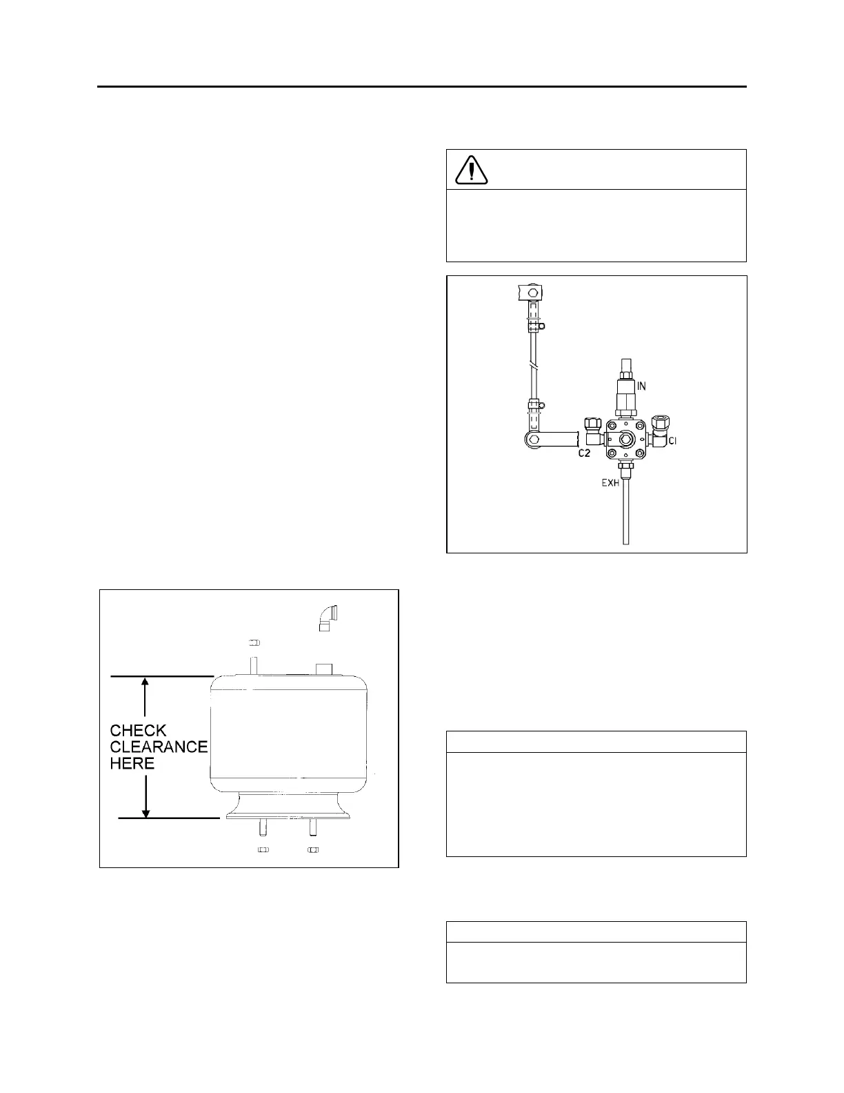
The appropriate vehicle body height is obtained
by measuring the clearance of all the air springs
installed on the vehicle. The two front air springs
clearance should be 11 ± ¼“ (279 ± 6 mm).
Refer to figure 24 to identify the correct area to
take measurement. The rear air springs
clearance should be 11 ½ ± ¼" (292 ± 6 mm).
FIGURE 24: TYPICAL AIR SPRING CLEARANCE 16058
At this point, it should not be necessary to make
an adjustment under normal service conditions.
However, if an adjustment is required, change
the position of the overtravel lever in relation to
the overtravel control body. The lever should be
moved up to raise vehicle height, and down to
lower it. Check that main air pressure is at
normal operating pressure and raise the vehicle
to the specified height.
CAUTION
Always adjust on "fill cycle". If it is necessary
to lower vehicle height, release sufficient air to
be well below height, and adjust to height or
fill cycle.
FIGURE 25: FRONT HEIGHT CONTROL VALVE 16100
The normal ride height is obtained by adjusting
air spring clearance of both front and rear
suspension as follows:
Front air spring clearance
1. With the vehicle at normal operating air
pressure [100 - 125 psi (689 - 860 kPa)],
measure air spring clearance. This
clearance should be 11 ± ¼“ (279 ± 6 mm).
NOTE
The measurement should be taken from
underneath the upper air spring support on
subframe to top of the lower air spring support
on axle (refer to figure 24 for more details). If
adjustment is required, begin with the drive
axle.
2. Loosen the clamp on the height control
valve rubber coupling and bring it up or
down (Fig. 25).
NOTE
Allow suspension to stabilize before taking
reading.