Section 12: BRAKE AND AIR SYSTEM
Section 12 Updated Sept. 2015 X3-45 Commuter PA1593 DOB 2400-2489 11
FIGURE 11: RD-3 12136
14. FLIP-FLOP CONTROL VALVE (TW-1)
A flip-flop control valve mounted on the L.H.
lateral console is provided to unload tag axle air
springs and to lift tag axle. It is a manually
operated "on-off" valve. Maintenance and repair
information on this valve is supplied in the
applicable booklet annexed to this section under
reference number SD-03-3602.
FIGURE 12: TW-1 12138
15. DUAL BRAKE APPLICATION VALVE
(E-10P)
The E-10P dual brake valve is a floor mounted,
foot-operated type brake valve with two separate
supply and delivery circuits. This valve is located
in the front service compartment (Fig. 13).
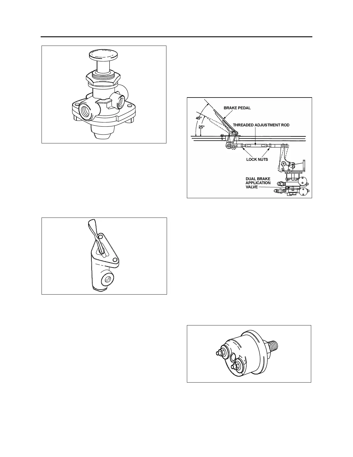
15.1 BRAKE PEDAL ADJUSTMENT
After brake pedal replacement or repair, adjust
the pedal to its proper position according to the
following procedure:
1. Replace the linkage, loosen threaded rod
lock nuts and screw or unscrew the threaded
adjustment rod in order to obtain a 45
o
brake
pedal inclination (Fig. 13).
2. Tighten threaded rod lock nuts.
15.1.1 Maintenance
Maintenance and repair information on the E-10P
dual brake application valve is supplied in the
applicable booklet annexed to this section under
reference number SD-03-830.
FIGURE 13: BRAKE PEDAL ADJUSTMENT 12208
16. STOPLIGHT SWITCHES
Two electro-pneumatic stoplight switches are
mounted on the dual brake application valve (E-
12). The upper one is used for the primary air
circuit while the lower one is used for the
secondary air circuit. Both switches are
connected in parallel and have the same
purpose, i.e. completing the electrical circuit and
lighting the stoplights when a brake application is
made. The upper switch (AC Delco) is designed
to close its contact between 2 psi and 4 psi (14
kPa to 28 kPa) (Fig. 14), while the lower one
(Bendix, SL-5) closes its contact at 4 psi (28
kPa) (Fig. 15). The switches are not serviceable
items; if found defective, the complete unit must
be replaced.
FIGURE 14: DELCO SWITCH 12139