Section 12: BRAKE AND AIR SYSTEM
24 X3-45 Commuter PA1593 DOB 2400-2489 Section 12 Updated Sept. 2015
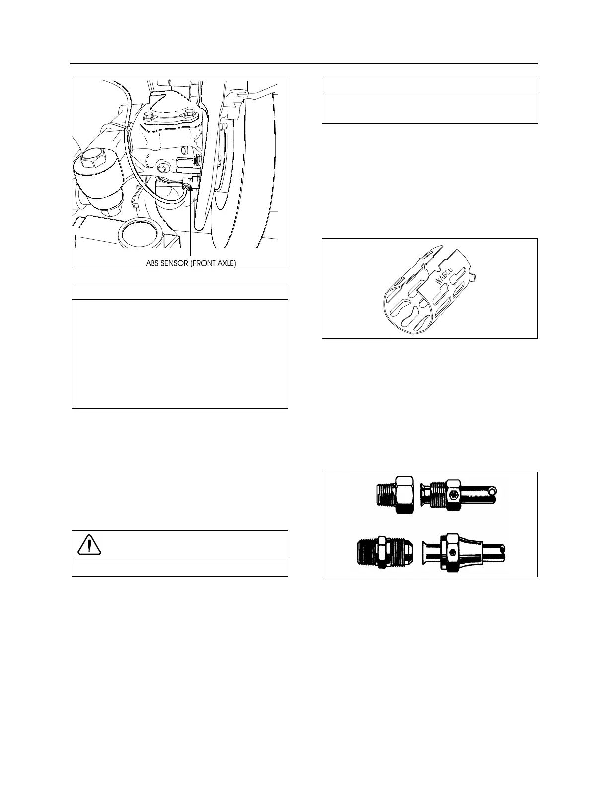
FIGURE 34: ABS SENSOR LOCATION 12153
The resistance value, when sensors are
checked as a unit, must be equal to 1,75 k
ohms. To check the sensors for proper output
voltage after the sensors and toothed wheels
have been assembled to the axle, connect a
suitable AC voltmeter across the output
terminals. With the hubs rotating at 30 rpm, the
output voltages should read from 50 to 1999
mV to be acceptable.
Sensor Installation
The following procedure deals with sensor
installation on the axle wheel hubs. Read
procedure carefully before reinstalling a sensor,
as its installation must comply with operational
tolerances and specifications.
1. Apply recommended lubricant (Prevost
#680460) to spring clip and sensor.
CAUTION
Use only this type of grease on the sensors.
2. Insert spring clip in the holder on hub. Make
sure the spring clip tabs are on the inboard
side of the vehicle. Push in until the clip
stops.
3. Push the sensor completely inside the spring
clip until it is in contact with the tooth wheel.
Ensure mounting is rigid, as it is an im-
portant criterion for adequate sensor opera-
tion.
This installation should be of the "press fit"
type.
31.2.4 Spring clip
The spring clip retains the sensor in its mounting
bracket close to the toothed pulse wheel. The
gap between the sensor end and teeth is set
automatically by pushing the sensor in the clip
hard up against the tooth wheel, and the latter
knocks back the sensor to its adjusted position
(Fig. 34).
FIGURE 35: SPRING CLIP 12161
Maintenance
The spring clip requires no specific
maintenance.
32. FITTING TIGHTENING TORQUES
45
Flare and Inverted Flare: Tighten assembly
with a wrench until a solid feeling is encountered.
From that point, tighten 1/6 turn (Fig. 35).
FIGURE 36: HOSE FITTINGS 12053