Section 01: ENGINE
PA1593
12
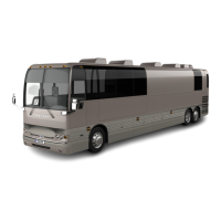
FIGURE 9: COOLER POSITION DURING ENGINE
CRADLE INSERTION OR REMOVAL
6. From underneath, unfasten the bolts fixing
the engine cradle.
7. Disconnect the engine coolant hose near
the starter.
8. Disconnect air compressor suction and
discharge hoses.
With Vehicle Lowered
Lower the vehicle enough to access all
components.
Engine Compartment R.H. side
Disconnect cables from two chassis
grounds located on diagonal member.
Inside engine compartment, disconnect
starter, alternators and heater cables.
Also disconnect AFSS cable if
applicable.
Disconnect from engine, connector
C398 and vehicle interface harness
connector located above EECU
connectors. Also disconnect DPF cable.
Disconnect power steering pump hoses.
Shut off fuel line shut-off valve.
Close engine fuel supply shut-off valve
on primary fuel filter. Disconnect the fuel
line located above fuel filters and
connected to inlet port.
Disconnect fuel return line located
above fuel filters.
Disconnect alternators cooling duct and
put aside.
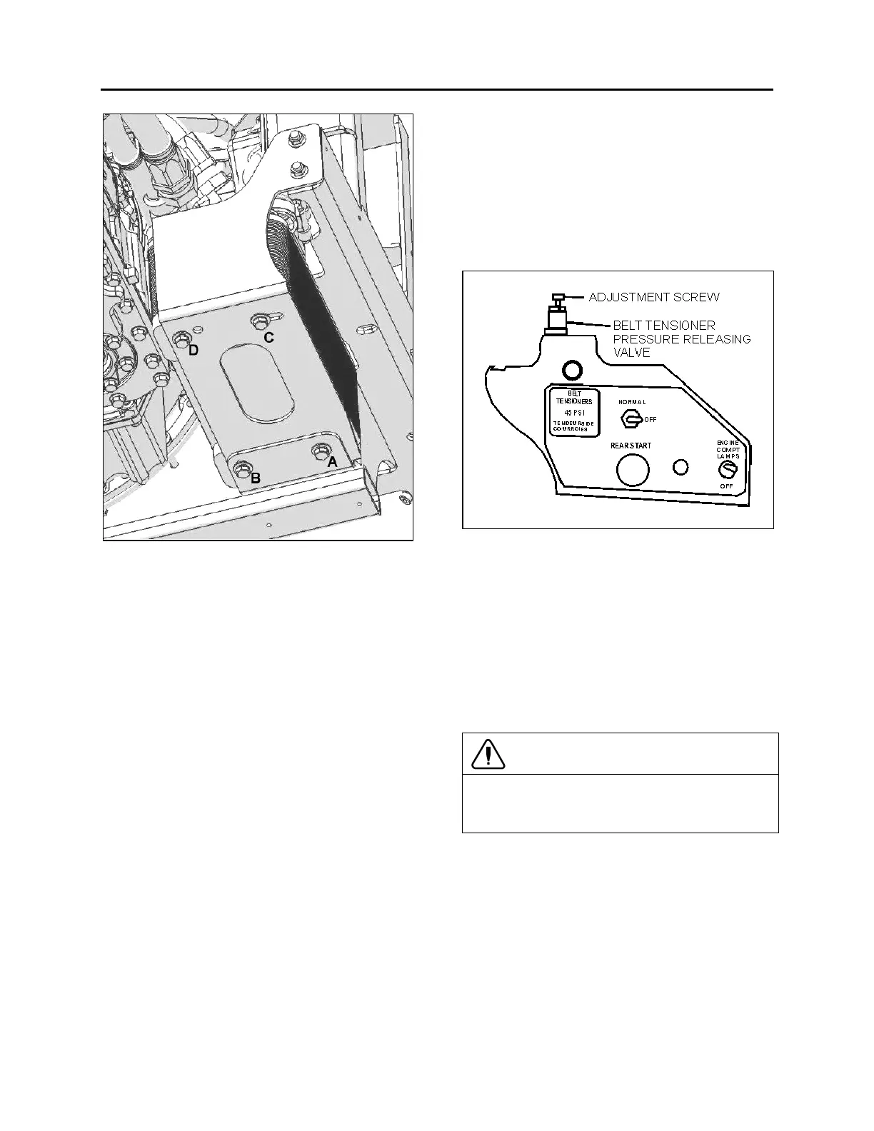
FIGURE 10: BELT TENSIONER VALVE 12200
Locate the A/C compressor belt
tensioner pressure releasing valve
(Fig. 10). Turn pressure releasing valve
handle counterclockwise in order to
release pressure in belt-tensioner air
bellows and loosen belts. Remove the
belts.
Disconnect and remove the engine-air
intake duct mounted between air
cleaner housing and turbocharger inlet.
CAUTION
To avoid damage to turbocharger, cover the
turbocharger inlet opening to prevent foreign
material from entering.
Disconnect and remove the exhaust
pipe mounted between the flexible
coupling and the pipe going to the
Diesel Oxidation Catalyst (DOC) and
Diesel Particulate Filter (DPF)
assembly. If necessary, refer to Section
4: EXHAUST SYSTEM under
“EXHAUST AFTERTREATMENT
SYSTEM OVERVIEW".
 Loading...