Section 22: HEATING AND AIR CONDITIONING
PA1593
6
NOTE
The driver’s area air temperature sensor is
located behind the grill of the R.H. side
console (Refer to fig.14).
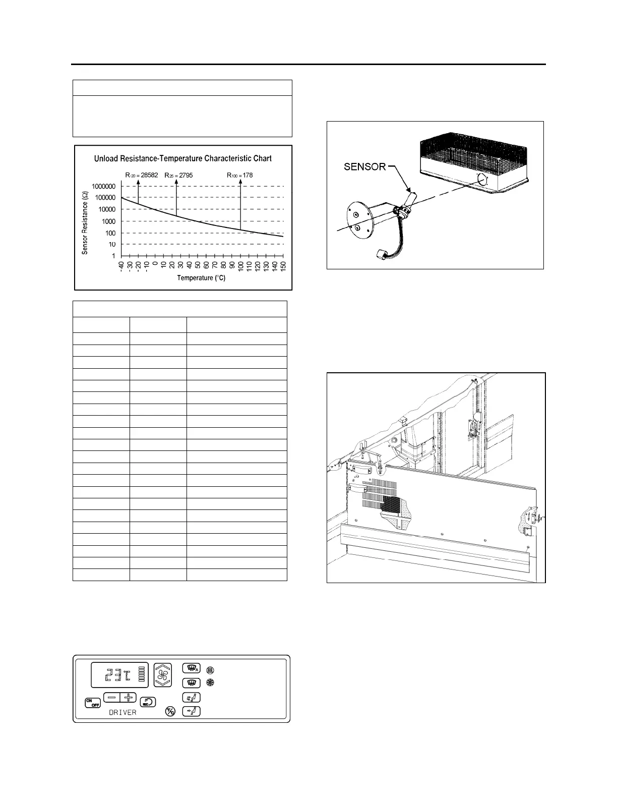
TEMPERATURE SENSOR
Temp °C Temp °F Resistance Ohms
-40 -40 100865
-35 -31 72437
-30 -22 52594
-25 -13 38583
-20 -4 28582
-15 5 21371
-10 14 16120
-5 23 12261
0 32 9399
5 41 7263
10 50 5658
15 59 4441
20 68 3511
25 77 2795
30 86 2240
35 95 1806
40 104 1465
45 113 1195
50 122 980
55 131 808
60 140 670
3.2 PASSENGERS’ SECTION OPERATION
The passenger’s section has a preset
temperature of 68°F (20°C).
FIGURE 5: CENTRAL HVAC SYSTEM CONTROL UNIT
Temperature control is provided in conjunction
with a thermistor sensor inside register duct,
located on L.H. side of vehicle (Figs. 3 & 6).
FIGURE 6: THERMISTOR SENSOR
The flow of water to the vehicle's main heater
core is controlled by a pneumatic water valve
which varies the cycling rate depending on
selected temperature. A red LED, located on
HVAC control unit, illuminates when heating
mode is selected. A green LED illuminates when
compressor clutch is in operation.
FIGURE 7: EVAPORATOR COMPARTMENT 22301
The evaporator fan motor, located in the
evaporator compartment, is protected by a 90
amps, manually-resettable (CB3) circuit breaker
located on the rear junction panel and is
accessible from the engine compartment curb-
side door, on R.H. side of the vehicle (refer to
Section 06, “Electrical System” in this manual for
details).
 Loading...