General
1. Unscrew and open the interface.
2.
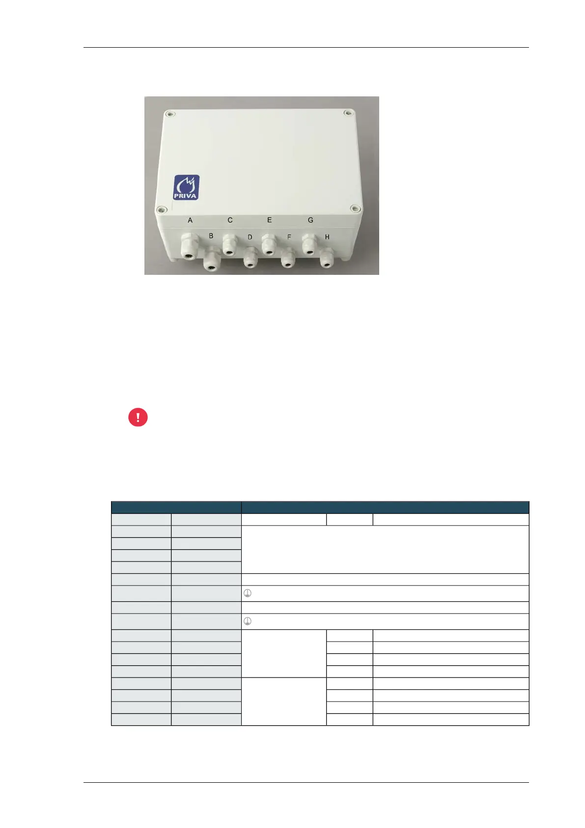
Cable glands of Weather interface WI2
E. Wind direction sensor A. 24 VAC power supply
F. Linear light sensor LS2WI B. Output signals to I/O module
G. Outside temperature sensor C. Rain sensor
H. Reserve D. Wind speed sensor
Feed the wiring for the 24 VAC power supply, sensors and output signals through the correct
cable glands; see the figure Cable glands of Weather interface WI2 (page 59).
3. Connect the wiring from the various components to the connector terminals of the interface.
Connect the output signals of the sensors to the universal inputs of the Priva Blue ID modules.
See table Connections of Weather interface WI2 (page 59).
The power supply for the Weather interface WI2 must not be delivered by the same
power supply that powers the controller.
4. Only for a Linear light sensor or Radiation sensor CM3P: set the Weather interface jumpers. See
Setting the Weather interface WI2 jumpers (page 61).
5. Screw the interface closed
Connections of Weather interface WI2
Sensors or power supplyWeather interface WI2
FunctionWire colourGroupNameConnector
24 VAC power supply for interface and sensors (electrically isolated)24 VAC IN1 HIGH
(24 VAC ± 15 %, 0.4 A, 10 VA)
0 VAC1 LOW
24 VAC IN2 HIGH
0 VAC2 LOW
24 VDC power supply for external devices (100 mA)24 VDC OUT3 HIGH
PGND3 LOW
24 VDC power supply for external devices (100 mA)24 VDC OUT4 HIGH
PGND4 LOW
Connection 1 heating elementWhiteRain sensorRGVW15 HIGH
Connection 2 heating elementBrownRGVW25 LOW
Connection 1 measurement patternGreenRGKM16 HIGH
Connection 2 measurement patternYellowRGKM26 LOW
24 VDC power supplyWhiteWind speed sensor24 VDC7 HIGH
GroundBrownGND7 LOW
SignalGreenWS IN8 HIGH
GroundYellowGND8 LOW
59Installing Priva Compass - 00.014
Weather interface WI2