pH interface
Connecting the pH interface
The installation and maintenance of the pH sensor is described in detail in the pH sensor
manual.
1. Connect the BNC connector of the pH sensor to the BNC connector of the pH interface.
2. Unscrew and open the pH interface.
3. Feed the cabling through the cable gland.
4. Connect the wiring of the universal input of the Priva Blue ID module and the power supply to
the connector terminals of the interface. Use a 6-core shielded cable with cores of 6 x 0.8 mm
(0.5 mm²).
5. Screw the interface closed.
Connecting the cable
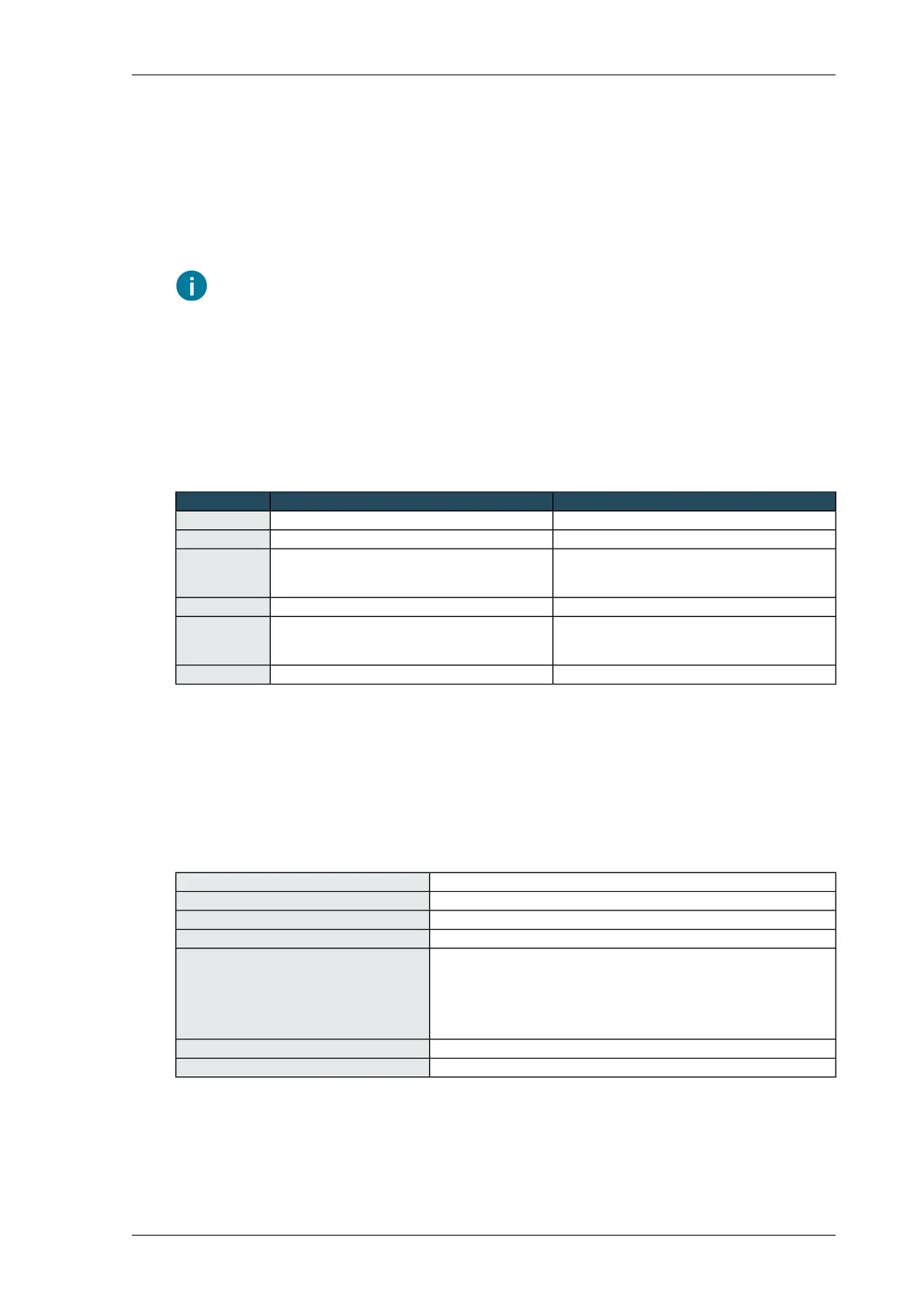
ConnectionFunctionName
FP or 24 VAC from external power supply24 VAC24V
FG or 0 VAC from external power supply0 VAC0V
UI
Add a pull-down resistor (100kΩ) to GND for cable
break detection.
sensor signal pH sensor 1PH1
FGpH sensor 1 GND (not electrically isolated)GND
UI
Add a pull-down resistor (100kΩ) to GND for cable
break detection.
sensor signal pH sensor 2PH2
FGpH sensor 2 GND (not electrically isolated)GND
Calibrating the pH interface
Calibrate the pH sensor using the Compass software. See the help text in the software.
Technical specifications - pH-interface
pH-interfaceArticle description
3771056Article number
aluminiumHousing material
85 x 120 x 120 mmDimensions H x L x W (without grommet)
on housing:
Connections
• 2 BNC-connectors for 2 pH-sensors (3770946)
on pH-interface board 9969:
• 24 VAC input power supply
• 2 analog outputs
24 VACSupply voltage
0 … 35 °CAmbient temperature
85Installing Priva Compass - 00.014
pH interface