USER’S MANUAL. PRODIG-5
Page 38 11/2006
10
0
-10
-20
EXITCALIBRATE
FREQ:
REF:
TEST:
ATT:
1042.25
84.7
84.5
0.2
1703.25
90.2
90.2
0.0
2108.25
99.1
1.2
100.3
MHz
dBuV
dBuV
dB
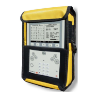
Figure 15.- SAT IF Test. Satellite band.
2.- MEASUREMENT OF THREE PILOTS THROUGHOUT THE NETWORK
Once PRODIG-5 (EXPLORER) has been calibrated, start to make level
measurements in the different distribution outlets using the EXPLORER. On the
screen will appear the attenuation values for the three pilot frequencies measured in the
outlet plate (see the following figure).
10
0
-10
-20
1042.25
84.7
80.7
4.0
1703.25
90.2
84.2
6.0
2108.25
100.3
77.6
22.7
MHz
dBuV
dBuV
dB
FREQ:
REF:
TEST:
ATT:
EXITCALIBRATE
Figure 16.- Attenuation measurements in an outlet plate.
In order to finish measuring, press the rotary selector [1] and select the (EXIT)
option.
 Loading...