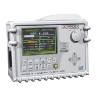
MANUAL DE INSTRUCCIONES. PRODIG-5
11/2006 Página 69
6 DESCRIPCIÓN DE ENTRADAS Y SALIDAS
6.1 Entrada de RF
La entrada de RF se realiza a través del conector [30] en el panel lateral.
El nivel máximo de la señal no debe superar, en ningún caso, 130 dBµV.
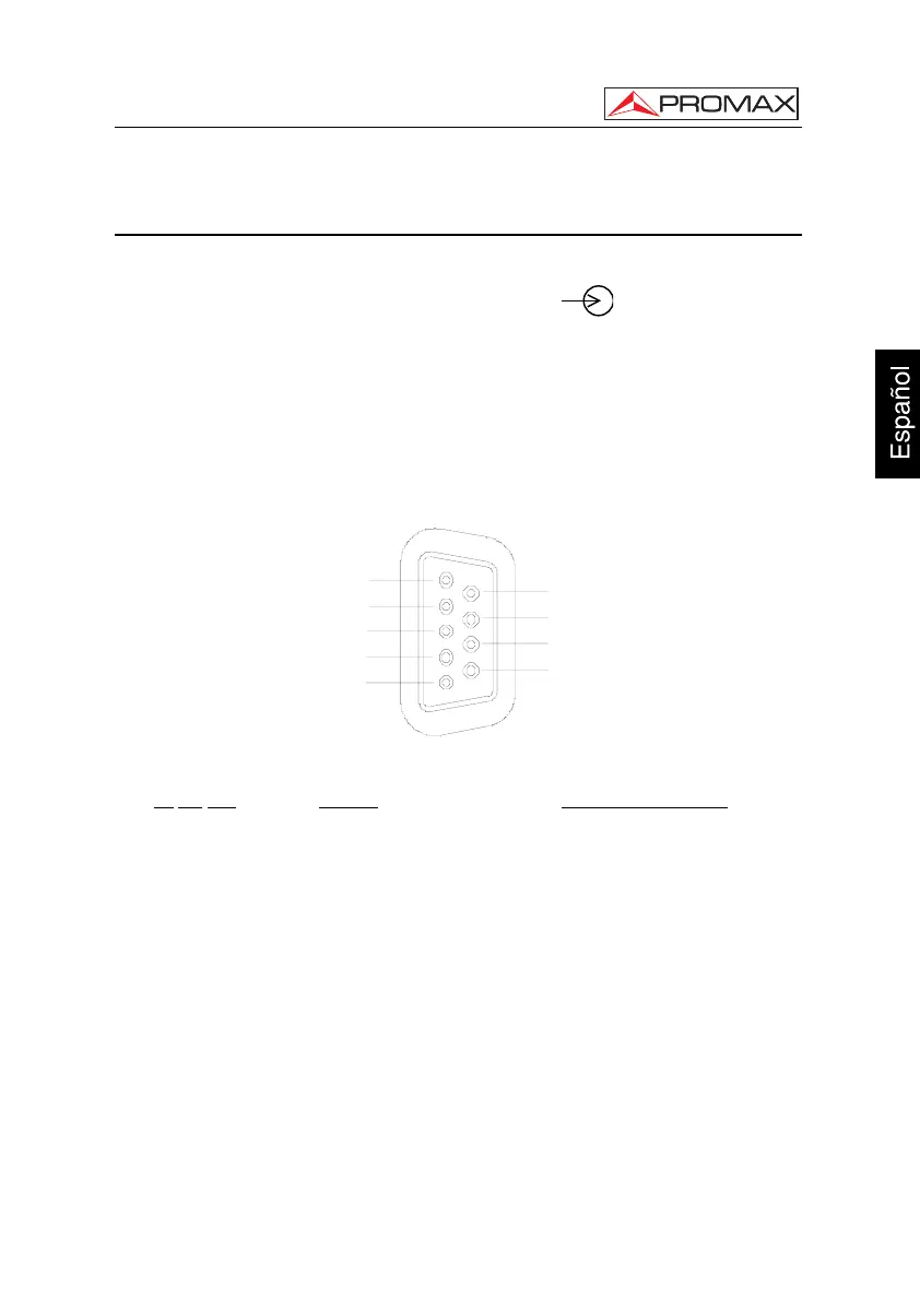
6.2 Puerto Serie RS-232C
El PRODIG-5
(EXPLORER) dispone de un puerto serie RS-232C para procesos de
diagnostico, ajuste y calibración.
Las señales en este conector se describen en la tabla 4.
1
5
3
2
4
9
8
7
6
Figura 42.- Conector RS-232C. Vista exterior.
Nº
DE PIN SEÑAL CARACTERÍSTICAS
1 Carrier Detect (no conectado)
2 Data Request (RxD)
3 Data Transmit (TxD)
4 Data Terminal Ready (DTR) (no conectado)
5 Masa del conector (GND)
6 Data Set Ready (DSR) (no conectado)
7 Request To Send (RTS)
8 Clear To Send (CTS)
9 Ring Indicator (no conectado)
Tabla 4.- Descripción del conector RS-232C.