MANUEL D’UTILISATION. PRODIG-5
11/2006 Page 67
Français
6 DESCRIPTION DES ENTRÉES ET DES SORTIES
6.1 Entrée de RF
L'entrée de RF se fait à l'aide du connecteur RF [30] sur le panneau
latéral. Le niveau maximal du signal ne doit pas être supérieur à 130 dBµV.
6.2 Port Série RS-232C
Le PRODIG-5
(EXPLORER) dispose d'un port de raccordement série RS-232C
pour les processus de diagnostic, calibrage et configuration.
Les signaux de ce connecteur sont décrits sur le tableau 4.
1
5
3
2
4
9
8
7
6
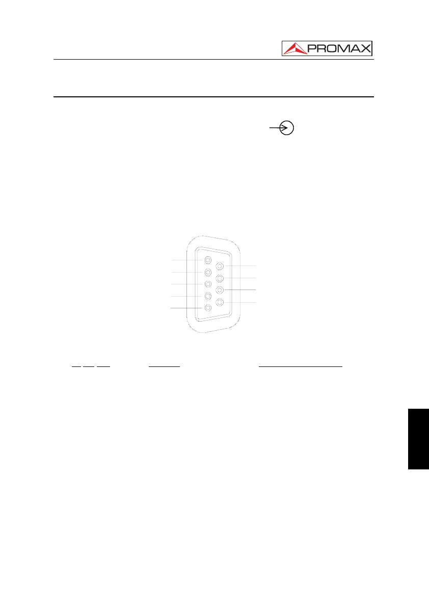
Figure 42.- Connecteur RS-232C. Raccordements vus de face.
Nº
DE PIN SIGNAL CARACTÉRISTIQUES
1 Carrier Detect (non raccordé)
2 Data Request (RxD)
3 Data Transmit (TxD)
4 Data Terminal Ready (DTR) (non raccordé)
5 Masse du connecteur (GND)
6 Data Set Ready (DSR) (non raccordé)
7 Request To Send (RTS)
8 Clear To Send (CTS)
9 Ring Indicator (non raccordé)
Tableau 4.- Description du connecteur RS-232C.
 Loading...