USER’S MANUAL. PRODIG-5
Page 68 11/2006
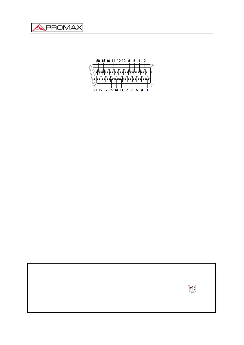
6.3 Scart (DIN EN 50049)
Figure 43.- Scart socket (external view).
Also known as PERITEL connector (in conformity with standard NF-C92250). The
signals in this connector are the following:
PIN number SIGNAL CHARACTERISTICS
1 Right channel audio output
2 Right channel audio input
3 Left channel audio output
4 Audio grounding
5 Blue grounding (B)
6 Left channel audio input
7 Blue output (B)
8 Switching voltage
9 Green grounding (G)
10 Digital bus interface (not connected)
11 Green output (G)
12 Digital bus interface (not connected)
13 Red grounding (R)
14 Digital bus reserved (not connected)
15 Red output (R)
16 Blanked signal (not connected)
17 Composite video grounding
18 Blanked return (not connected)
19 Composite video output
20 Video input
21 Connector shield grounding
Table 5.- Description of the Scart.
NOTE: In order to select the SCART connector operation mode between: video
Input, video Output or Automatic, from the TV visualisation mode [10]
follow the following steps:
1) Select the Measurement Configuration menu by pressing the [17] key
and verify that the type of signal selected is ANALOGUE.
2) Select the suitable operation mode for the SCART by means of the
Video/Aud Ext option in this menu.
 Loading...