The behaviour is factory-programmed. If another switching function is
desired, the pump can be reprogrammed in the
‘Relay’
menu.
The relay can be retrofitted and is operational once it has been plugged
into the relay board.
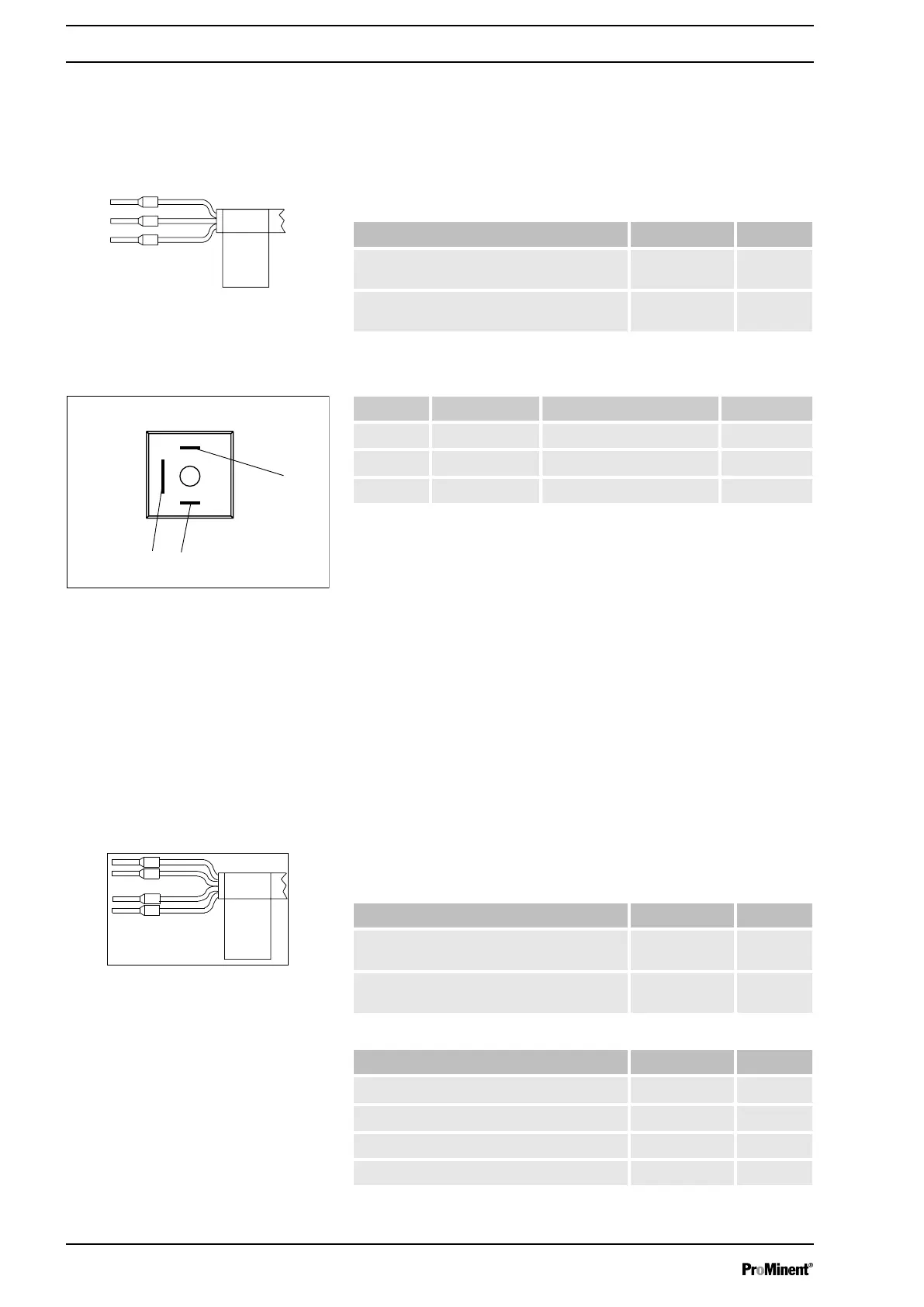
Electrical interface
Data Value Unit
Maximum contact load at 230 V and 50/60
Hz:
8 A
Minimum mechanical service life: 200,000 switching
operations
To pin VDE cable Contact CSA cable
1 white N/O (normally open) white
2 green N/C (normally closed) red
4 brown C (common) black
9.2.6.3 Output for other relays (identity code 4)
A fault indicating and a pacing relay can be ordered as options - refer to
ordering information in the appendix. The pacing output is electrically iso‐
lated by means of an optocoupler with a semiconductor switch. The
second switch is a relay (also electrically isolated).
The behaviour is factory-programmed. If another switching function is
desired, the pump can be reprogrammed in the
‘Relay’
menu.
The fault indicating/pacing relay can be retrofitted and is operational once
attached to the relay board - refer to the "Retrofitting relays" supplemen‐
tary instructions.
Electrical interface
for fault indicating relay output:
Data Value Unit
Maximum contact load at 24 V and 50/60
Hz:
2 A
Minimum mechanical service life: 20,000,000 switching
operations
for semiconductor switch pacing relay:
Data Value Unit
Max. residual voltage at I
off max
= 1 µA 0.4 V
Maximum current 100 mA
Maximum voltage 24 VDC
Pacing pulse duration, approx. 100 ms
Fig. 20: Assignment on cable
Identity code 1
Fig. 21: Assignment on pump
Fig. 22: Assignment on cable
Installation, electrical
36