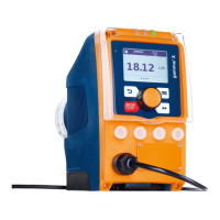
The "CANopen bus connection" takes place via a five-pin plug.
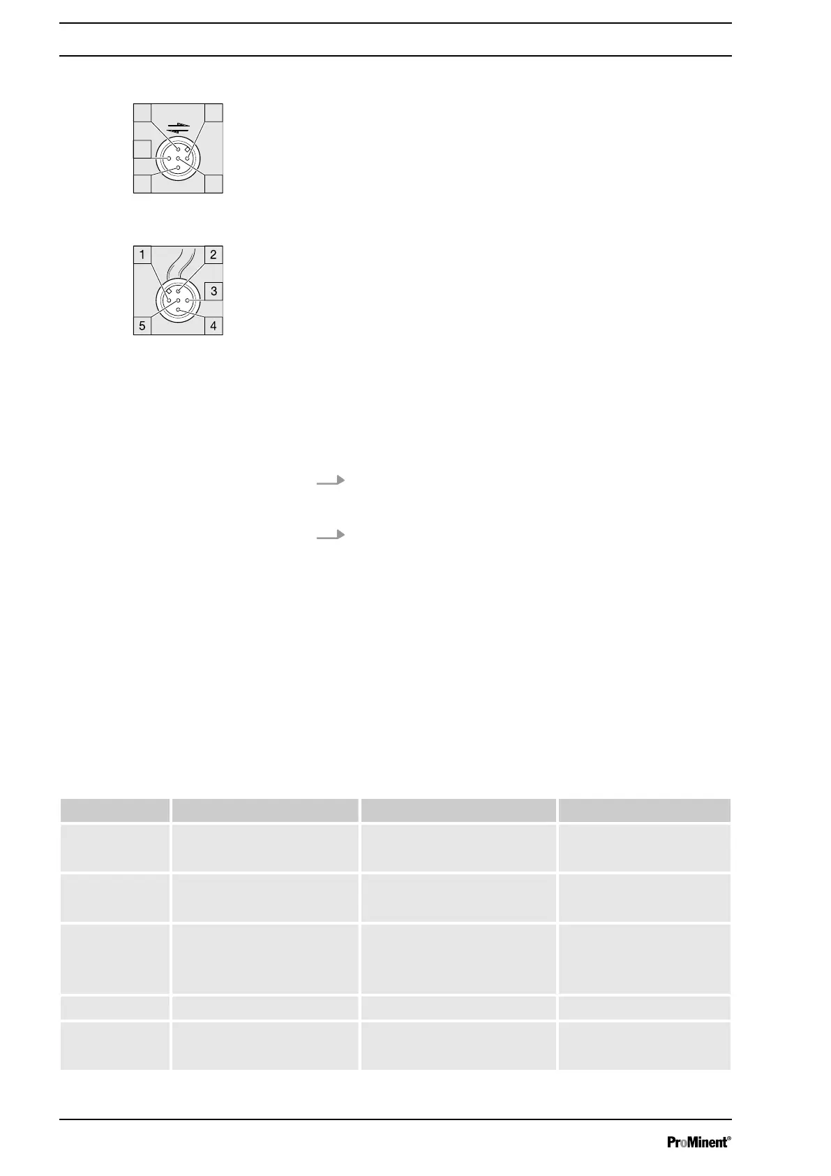
1 Shielding
2 CAN V+ (supply voltage – not connected)
3 CAN GND (reference potential)
4 CAN H (bus line - dominant high)
5 CAN L (bus line - dominant low)
2.4 Emergency mode
You can guard against the possibility of the CANopen bus control
failing in the following way:
1. Program an auxiliary frequency into the pump that fits opti‐
mally with a stroke length of 30 ... 100 % into your process in
emergency operation.
2. As soon as emergency operation is required, run the pump
using the "external control" socket on the auxiliary frequency
- see "Operating Instructions for Solenoid Metering Pump
gamma/ X GMXa" - "Installation, electrical".
2.5
Troubleshooting
The CANopen status LED indicates the status of the CAN connec‐
tion.
The display for operating and fault status is carried out using 3
other LEDs - see "Operating Instructions for Solenoid Metering
Pump gamma/ X GMXa“.
Tab. 3: Flash code CANopen status LED, top
Colour Flash code Cause Remedy
green illuminated Bus status
OPERATIONAL
- (Pump normal operation)
green flashing * Bus status
PRE-OPERATIONAL
wait briefly or start the
pump over the bus
green Single flashing ** Bus status
STARTUP
wait briefly of set the
pump for active bus ope‐
ration - see "Set-up"
chapter
green off Error (BUSOFF, Error,…) CAN bus test
green flickering Bus status
INIT
wait briefly
CANopen-Bus connector
Fig. 5: Pump pin assignments (male)
Fig. 6: CAN cable assignments
(female)
Supplementary Operating Instructions CANopen
18
 Loading...