© İnnosis Makine 40
Fig.21. Hammer group structure 1-5
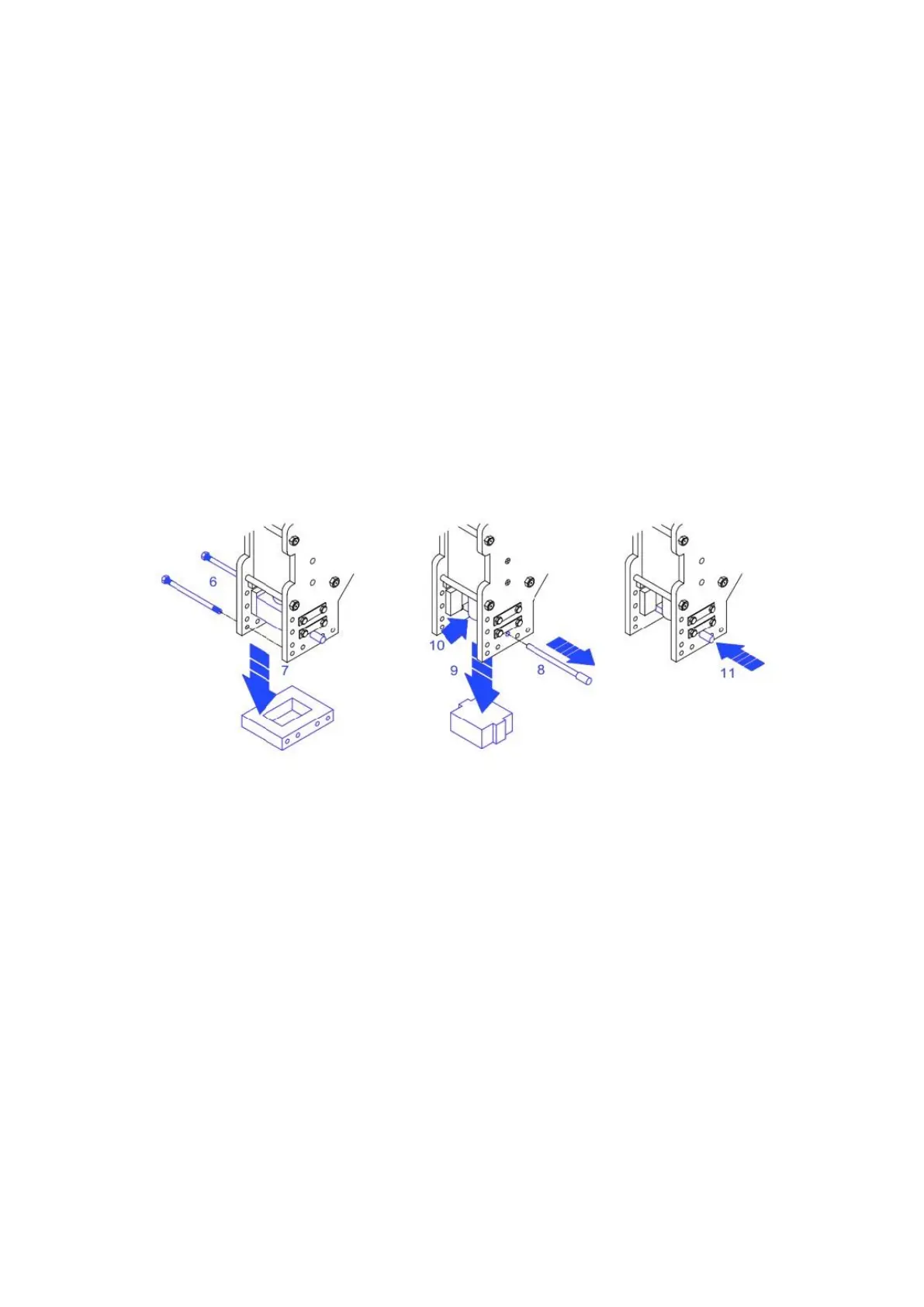
• Holding the pile hammer template sll with one hand, extract the two pins that x it to
the hammer group structure (6). Aer that, remove the template out of its seat (7), as
showed in gure 22.
• Holding the pile hammer sll with one hand, extract the bearing pin out of its seat (8)
and put it on a mobile table. Aer that, remove the pile hammer (9) carefully with the
other hand and make sure the pile head does not fall down (10)
• Hold the pile head sll and insert the bearing pin again in the appropriate hole (11) in
order to block the descent of the bit. Next , mount the new pile hammer and the new
pile hammer template. This can be done inverng the above described operaon.
Fig.22. Hammer group structure 6-11
4-2 Replacement and ghtening of the Tracks
Replacement
The crawler track must be replaced when there are 10 mm of tread le, but also previously to
the presence of cuts. For such replacement it is necessary to li the pile driver up from the
ground for at least 40 cm. The liing of the machine shall be done by hydraulic jacks.
Proceed with the substuon of the crawler track in following way: