Do you have a question about the Rational CombiMaster Plus CMP and is the answer not in the manual?
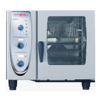
Model | CombiMaster Plus CMP |
---|---|
Brand | Rational |
Type | Combi Oven |
Cooking Modes | Convection, Steam, Combination |
Temperature Range | 30-300°C |
Capacity | Varies by model (e.g., CMP 61, CMP 101, CMP 201) |
Power Supply | Varies by model, typically 3-phase or single-phase options available |
Capacity (Pans) | Varies by model (e.g., 6 x 1/1 GN, 10 x 1/1 GN, 20 x 1/1 GN) |
Power Consumption | Varies by model (kW rating depends on size and voltage) |
Interior Dimensions (W x H x D) | Varies by model |
Exterior Dimensions (W x H x D) | Varies by model |
Weight | Varies by model |
Water Connection | 3/4" connection, cold water |
Introduction to the training manual covering SelfCookingCenter® and CombiMaster® Plus appliances.
Emphasizes technician training, adherence to regulations, and electrical/gas safety checks.
Details safety procedures for chemical use, gas component checks, and error message references.
Identifies key components in the SCC block diagram, including sensors, motors, and valves.
Details components shown in the SCC_XS 60 block diagram, covering various parts.
Identifies components within the CM_P Index I block diagram, such as thermocouples and sensors.
Illustrates block diagrams for CM_P 60 and CM 61/101, detailing their components.
Explains the operator panel layout, including the central dial, ON/OFF switch, and various keys.
Identifies humidity solenoid, pressure sensor, thermocouples, and safety thermostats.
Identifies PCBs, TFT display, CPU, door switch, and care pump.
Identifies steam generator, power supply, main PCB, SSR, and cooling fan.
Locates safety thermostat, cabinet sensor, steam inlet, fan wheel, and heating element.
Details selecting cooking modes and adjusting temperature settings.
Provides steps and cautions for descaling the steam generator using CALC.
Identifies solenoid humidity, level electrode, thermocouple, thermostats, and pressure sensor.
Locates CleanJet pump, SC pump, solenoids, contactor, noise filter, and SSR.
Identifies PCB, potentiometer, and door contact switch.
Locates safety thermostat, cabinet sensor, steam inlet, fan wheel, and heating element.
Illustrates water level control systems for SC_WE and CM_P units, showing key components.
Details the automatic self-test process, its components, and prerequisites.
Explains how to start manual humidity calibration and the boiling point calculation process.
Details steam control methods and humidity control based on pressure sensor P1.
Shows wiring diagrams for the Interface PCB (A1) and Main PCB (A2).
Explains how to access service modes, enter passwords, and view diagnostic data.
Explains how to navigate service levels and function tests using DIP switches and timer dial.