- 51 - V08 en, SCC
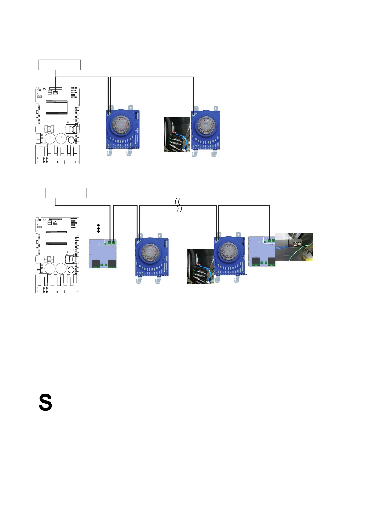
Electric units:
1 2
1 2
Gas units Bottom motor
4 1 2 8
Bottom motor and bottom ignition box
The bus system is equipped with a 6-pol Mini-Fit plug system.
In the bus system the individual components have individual addresses. Each address only exists once in a unit.
On units 201 and 202 the bottom fan motor and the bottom ignition box are identied by a jumper. This jumper
is part of the control harness.
The main pcb sends the action command via the bus cable. Additionally the pcb receives information from the
individual components via the same bus ( e.g. rpm).
In case the component does not respond to the bus signal an error Service 34.x will be shown.
The two bus connections on the motor and ignition box are equal and can be chosen freely.
Error 34.x: failure of BUS communication between PCB and other BUS components. Check the power sup-
ply, the LED and the BUS cable on the components. When the error number changes aer changing
the bus cable sequence, one of the bus cables is defective.
A combination of errors is possible: e.g. 34.10 No bus communication with bottom motor and bottom
ignition box. Please refer to fault tree!
Please apply contact grease 9003.0219 to bus cable plugs
Keep the bus cable away from hot surfaces. In case of an internal bus short circuit pcb, motor or ignition box
can be damaged!
Note: SCC Index E-G has an additional I/O pcb (address 1) connected to the bus system. In that unit the top
motor has BUS number 2, the bottom motor number 4 etc.
61-102 G 201-202 G
1
1
1
1
1
+
+
+
159
1
11
2
1
1
160
V34
L4
L3
F1
F2
K4
K11
K2
K5
K3
K7
X27
CR 2032
V28
V33
V29
11
X12
X1
X8
X
75B
K1
K6
K9
K12
X51
K10
K8
X26
X15
25
X30
IC
24
X16
X6
X2
X3
X5
X4
V68
V10
V68
X54
X53
Counting:
X29
X107
X106
1
1
SCC 61-102: A7
61-102 E
1
1
1
1
1
+
+
+
159
1
11
2
1
1
160
V34
L4
L3
F1
F2
K4
K11
K2
K5
K3
K7
X27
CR 2032
V28
V33
V29
11
X12
X1
X8
X75 B
K1
K6
K9
K12
X51
X75A
K10
K8
X26
X15
25
X30
IC
24
X16
X6
X2
X3
X5
X4
V68
V10
V68
X54
X53
Counting:
X29
X107
X106
1
1
201-202 E
SCC 61-102: A7
Bus connection