V08 en, SCC - 6 -
B3.1 - 3.6
F4
P1
M4
M6
Y2
Y3
B2
M1
S2
M7
S12
B4
B5
F3
S3
Y4
S11
M12
Care
Y5
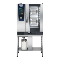
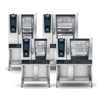
SCC
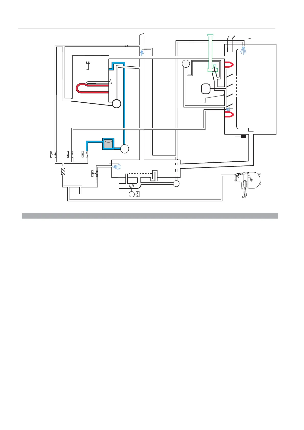
Block diagram SCC
B1 Thermocouple interior cabinet
B2 Thermocouple control box
B3.1-B3.6 Thermocouples core temperature
B3 Thermocouples core temperature (CM_P)
B4 Thermocouple humidity
B5 Thermocouple steam generator (preheat, 180°C (356°F) max)
F3 Safety thermostat steam generator 160°C (320°F)
F4 Safety thermostat interior cabinet 360°C (680°F)
M1 Fan motor (Floor unit: top)
M2 Fan motor (Floor unit: bottom)
M4 SC-pump
M6 CleanJet pump (SCC_WE)
M7 Motor drain valve / ball valve (SCC_WE)
M12 Care pump (SCC_WE)
S2 Level electrode
S3 Door reed switch
S11 CDS sensor (SCC_WE)
S12 Micro switch drain valve
P1 Dierential Pressure sensor humidity
Y1 Solenoid valve lling
Y2 Solenoid valve control box
Y3 Solenoid valve moistening (SCC_WE)
Y4 Solenoid valve Care (SCC_WE)
Y5 Solenoid valve Clima