- 7 - V08 en, SCC
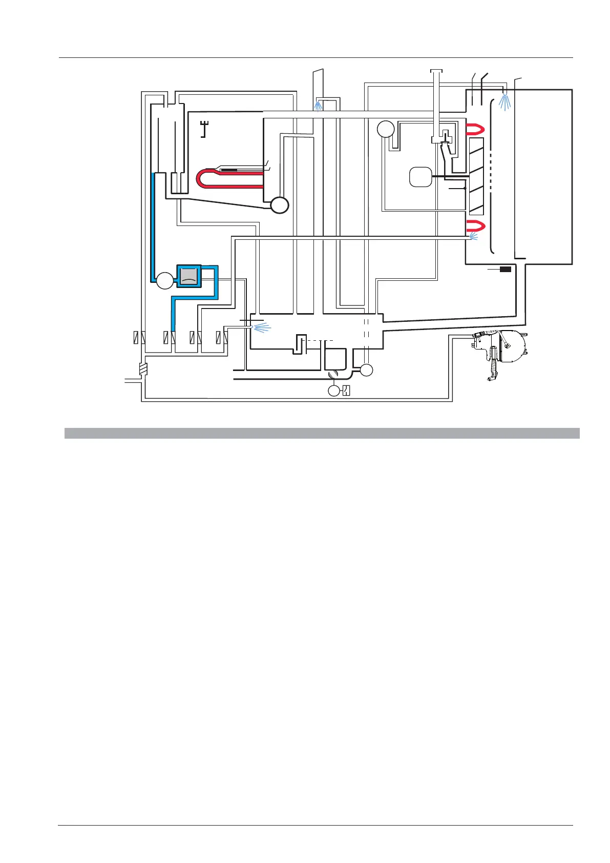
B1
B3.1 - 3.6
F4
P1
M4
M6
B2
M1
M7
S12
B4
B5
F3
S3
M12
Care
Y4
Y5
S11
Y1 Y3 Y2
S2
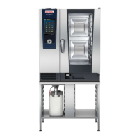
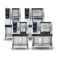
SCC_XS
Block diagram SCC_XS 60
B1 Thermocouple interior cabinet
B2 Thermocouple control box
B3.1-B3.6 Thermocouple core temperature
B4 Thermocouple humidity
B5 Thermocouple steam generator (preheat, 180°C (356°F) max)
F3 Safety thermostat steam generator 160°C (320°F)
F4 Safety thermostat interior cabinet 360°C (680°F)
M1 Fan motor
M4 SC-pump
M6 CleanJet pump
M7 Motor drain valve / ball valve
M12 Care pump
S2 Level electrode
S3 Door reed switch
S11 CDS sensor
S12 Micro switch drain valve
P1 Dierential Pressure sensor humidity
Y1 Solenoid valve lling
Y2 Solenoid valve control box
Y3 Solenoid valve moistening
Y4 Solenoid valve Care
Y5 Solenoid valve Clima