V08 en, SCC - 8 -
CM_P
61 - 202
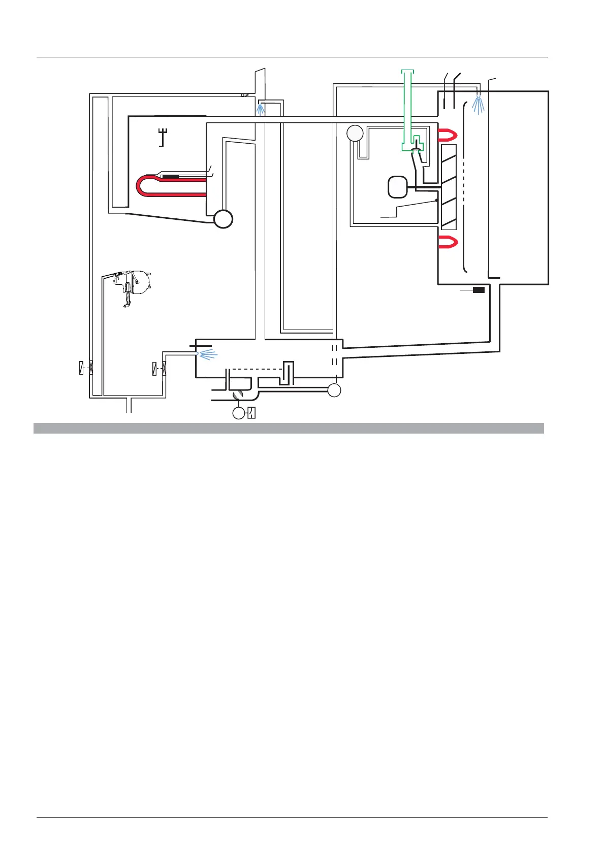
Block diagram CM_P Index I
B1 Thermocouple cabinet
B2 Thermocouple control box
B3 Thermocouple core temperature
B4 Thermocouple humidity
B5 Thermocouple steam generator
F3 Safety thermostat steam generator 160°C (320°F)
F4 Safety thermostat interior cabinet 360°C (680°F)
Y1 Solenoid valve lling
Y2 Solenoid valve quenching
Y5 Solenoid valve humidity
M1 Fan motor (without jumper)
M4 Pump SC-Automatic
M6 Cleanjet pump
M7 Drain valve
P1 Dierential pressure sensor
S2 Level electrode
S3 Door contact switch
CM_P 201/202 only:
M2 Fan motor bottom (with jumper)
B3
F4
P1
M4
M6
Y2
B2
M1
S2
M7
S12
B4
B5
F3
S3
Y5