Assembly
Hydraulic connection
43
5.7 Hydraulic connection
Pos: 59 /ZINDEL/Rollref fanlagen/Montage/ Motorsteuerung @ 1\ mod_1401781467063_1 3349.docx @ 13993 @ 3 @ 1
5.7.1 Motor control
Risk of uncontrolled system operation
Risk of being crushed by the furling system.
Controls for switching on the hydraulic drive must allow push-button operation only.
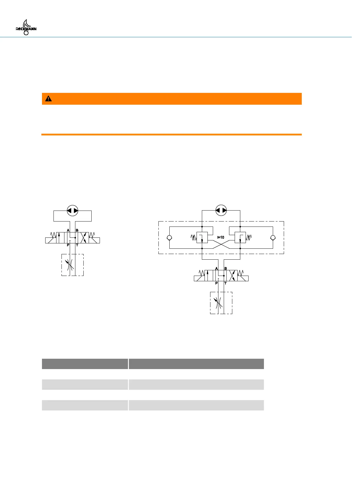
The hydraulic motor for the furling system is controlled by a 4-way 3-position directional valve with
float centre.
For furling systems RF90-4 and RF90-5 a valve block with two load control valves must be installed
as close as possible to the hydraulic motor. The valve block must have a control ratio of i = 10 and
an adjustment range of 70 bar to 175 bar.
RF 90-2, RF 90-3 RP90-4, RF90-5
The flow rate must not exceed the value given in the table below. If the hydraulic power pack has a
higher performance, a throttle valve must be installed in the pressure line of the directional valve.
Maximum flow rate
Furling system Maximum flow rate (l/min)
RF90-2 10
RF90-3, R40 foil 11
RF90-3, R5 foil 17
RF90-4 40
RF90-5 40 … 50
Pos: 60 /ZINDEL/Rollref fanlagen/Montage/ Hydraulikschlä uche anschließen @ 1\mod_140 1780825152_13349. docx @ 13992 @ 3 @ 1