COPYRIGHT © 2014 RED.COM, INC
RED DSMC OPERATION GUIDE
955-0020_V5.2, REV-G | 94
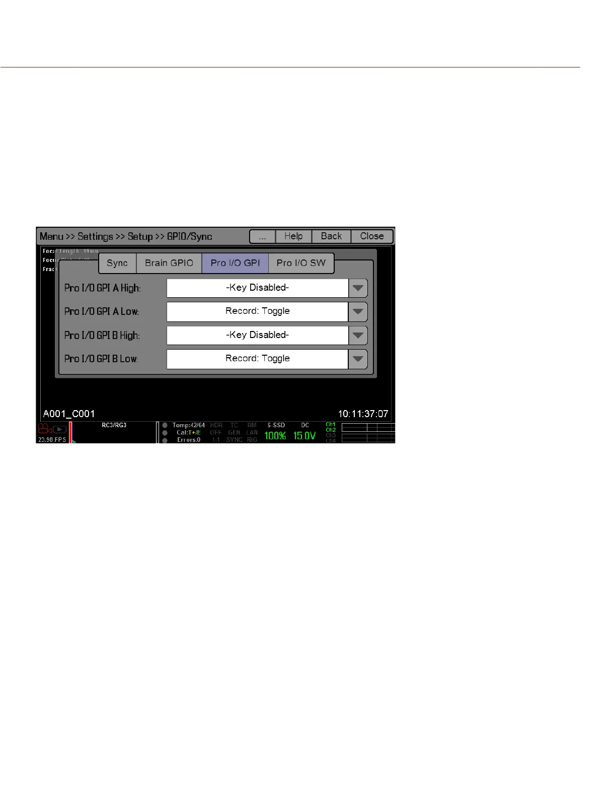
PRO I/O GPIO AND PRO I/O SW
Use the PRO I/O GPI and PRO I/O SW menus to map input and output (I/O) actions to the GPIO and AUX
connectors on the Pro I/O Module.
Low and High refer to the voltage. In practice, Low/High correlate to the press/release of a trigger or the on/
off position of a switch.
Low: The falling edge (transition from high voltage to low voltage).
High: The rising edge (transition from low voltage to high voltage).
For example, if you connect a start/stop trigger to the GPIO connector on the Pro I/O Module and keep the
default GPIO A High and Low settings (Key Disabled and Record: Toggle, respectively), then pressing the
trigger starts/stops recording.
 Loading...