— English Variomat Touch — 09.09.2022-Rev. C
3 Secondary vessel
4 Reflex rapid-action coupling R 1 x 1
5 Primary vessel
6 Primary vessel connection set
7 Typical representation of the control unit
EC Degassing line
• Gas-rich water from the system
• Degassed water to the system
LIS "LIS" level sensor
WC Make-up pipe
MAG Pressure expansion vessel
If required, install a diaphragm expansion vessel MAG ≥ 35 litres (Reflex N, for
example). It reduces the switching frequency and can be also used in the
individual protection of the heat generators. According to DIN / EN 12828, the
installation of valves between the device and the heat generator is required for
heating systems. Otherwise secure locking mechanisms must be fitted.
"EC" expansion lines
Because of the degassing function, you must install two "EC" expansion lines.
• One line to the system for the gas-rich water.
• One line to the system for the degassed water.
The "DN" nominal connection diameter for the "EC" expansion lines must be
designed for the "P
0
" minimum operating pressure.
Calculation P
0,
8.2 "Variomat switching points", 40.
The "DN" nominal connection diameter applies to an expansion line length of up
to 10 m. Beyond this length, select the next larger dimension. Integrate with the
"V" main flow volume of the system. Viewed in the system flow direction, the
gas-rich expansion line must be connected upstream of the expansion line
transporting the degassed water.
Ensure that particulate dirt cannot enter and thus creating an overload of the
"ST" dirt trap. Connect the "EC" expansion lines according to the following
installation variants.
Minimum operating
pressure p
0
(bar)
-1 X --- ---
-2/35 X --- ---
-2 ≤ 3.5 --- X ---
-2 > 3.5 --- --- X
Note!
The water temperature at the connection point of
the "EC" expansion
lines must be in the range of 0 °C to 70 °C. The use of auxiliary vessels
does not increase the range of use. Because the thermal protection is
not ensured due to the flow during the degassing phase.
7.3.4.2 Make-up line
If you don't connect the automatic water make-up, you must close the
connection of the "WC" make-up line with a R ½ " blind plug.
• Prevent a potential device fault by ensuring manual water make-up.
• Install at least one "ST" dirt trap with a mesh size ≤ 0.25 mm close
upstream to the make-up solenoid valve.
– Install a short line between the "ST" dirt trap and the solenoid valve.
Use a pressure reducer in the "WC" make-up line if the idle pressure
-up water from the potable water system, you may need
the Reflex Fillset for the "WC" make
-up line, 4.6 "Optional equipment
", 30.
Reflex make-up systems such as Reflex Fillset are designed for
make-up lines with a flow rate < 1 m³/h.
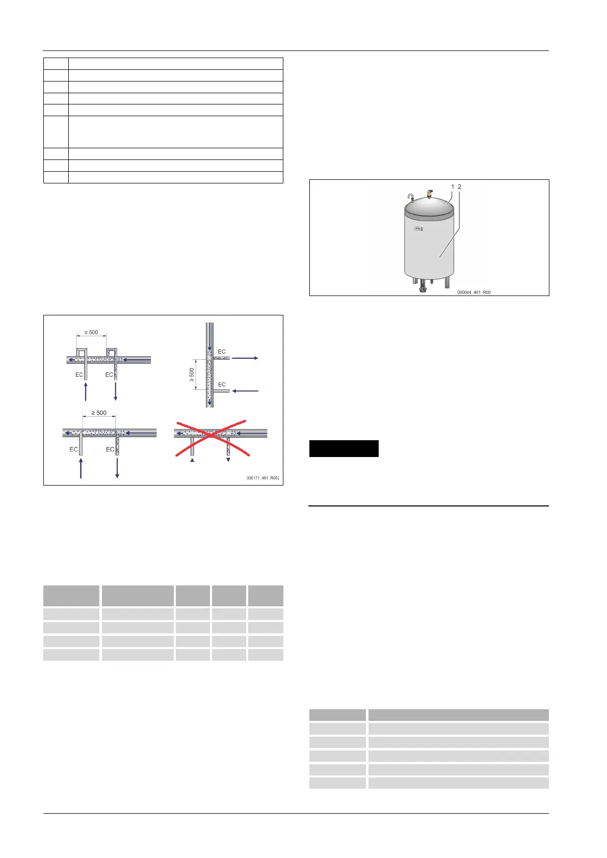
7.3.5 Fitting the thermal insulation
Install the optional thermal insulation (2) around the primary tank (1) and close
the insulation with the zip fastener.
Note!
For heating systems, insulate the primary tank and the "EC" expansion
lines against heat loss.
Thermal insulation is not required for either the primary tank top
-site, install thermal insulation when condensate forms.
7.3.6 Installation of the weight measuring cell
Damage to the pressure load cell due to unprofessional installation
Incorrect installation may result in damage to the "LIS" level sensor,
malfunctioning and incorrect measurements from the pressure load cell.
• Comply with the instructions regarding the installation of the pressure
The "LIS" level measurement uses a pressure load cell. This pressure load cell is to
be installed after the primary vessel has been placed at its final position, 7.3.3
"Tank installation", 34. Comply with the following instructions:
• Remove the transport safety device (squared timber) at the mounting foot
of the primary vessel.
• Replace this transport safety device with the pressure load cell.
– The pressure load cell can optionally be fastened to the mounting
foot of the primary vessel using the supplied screws. However,
fastening is not necessary.
• Avoid shock-type loading of the pressure load cell by, for example,
subsequent alignment of the vessel.
• Use flexible hoses to connect the primary vessel and the first secondary
vessel.
– Use only the supplied connection sets, 7.3.3 "Tank installation",
34.
• Perform a calibration of the filling level when the primary vessel is aligned
and fully emptied, 8.6 "Parametrising the controller in the Customer
menu", 42.
Standard values for level measurements:
200 l 0 – 4 bar
300 – 500 l 0 – 10 bar
600 – 1000 l 0 – 25 bar
3000 – 5000 l 0 – 100 bar
 Loading...
